
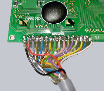
The wire has to be soldered to the 20×4 rows display like this…
In order that nothing can go wrong i indicate all colors. Pin1 black and ground, Pin2 red, Pin3 grey, Pin4 green-brown, Pin5 blue, Pin6 brown, Pin7 yellow-brown, Pin8 green, Pin9 yellow-white, Pin10 pink, Pin11 grey-brown, Pin12 purple, Pin13 green-white, Pin14 yellow, Pin15 blue-red, Pin16 white.
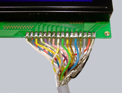
That’s it! Here is the pinout of the other side of the display.
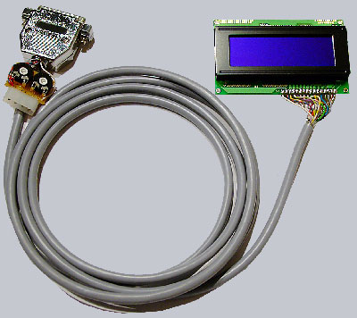
And here is a picture of the finished display with controller plate, power connector and parallelport connector:
If you connect everything to the pc an power it on, the first and third row of the display will already light up which means that it does not get a signal from the pc yet but is already powerd on. On the next page of the guide I described which software you are able to use, to control the display. The LCD-Displays in the fanshop have a slightly blue/purple background and are because of that a realy beautiful decoration at or in the pc which can for example be mounted in a 5 1/4 inch slot, or it can just be put on the table with a small acrylic stand. If you have enough space above the number block in your keyboard it would look great if you put it there and is, with the right software a really useful implement to show many different kinds of data like free disc space, up and download speed or the total amount of the downloaded data, any temperature, CPU-Speed, rounds per minute of the fans, free Windows ressources, music-titles, level indicators, Spielstände bei LAN-Games, a magnificent clock and many more different things . Owing to ever more extensive functions in the software almost no wish remains open.
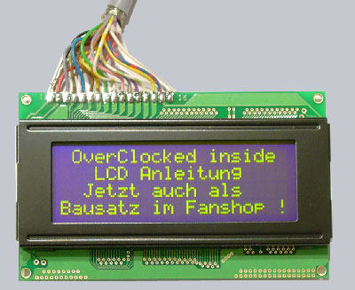
This is what the display with green/yellow LED backgroundlighting from the fanshop looks like at daylight:
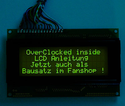
This is what the display with green/yellow LED backgroundlighting from the fanshop looks like in darkness:
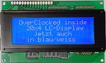
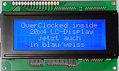
and here is a picture of the newer Fanshop display with white writing and shiny blue background:
Here you can see the first tests with an older LCD and some tools …