
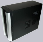
Now let’s get to the optical and practical criteria of the Sunbeamtech Tuniq2 case. The black metall case is very well finished and offers one 3.5 inch floppy drive expansion bay and eight 5.25 inch drive bays for the DVD-ROM, DVD writer, HDD mounting frames, etc behind the front bezel.
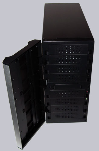
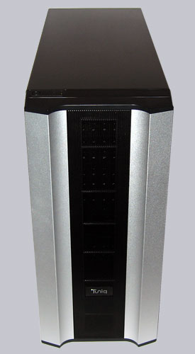
The front bezel looks very solid and the aluminium finish is really nice, whereby the middle of the front bezel is a perforated metal plate to ensure a good airflow.
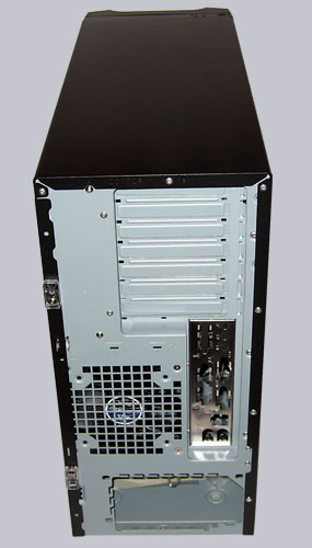
PC freaks will recognize within seconds that the back of this case is rather unusal, because the power supply unit is BTX like at the bottom of the case and not at the top – anyway, this is no BTX case. So the complete arrangement of the components is changed and the motherboard is installed upside down. This is the reason why you’ve to open the “wrong” side panel to get access to the installed hardware. Surely it’s questionable whether this arrangement is favourable, since e.g. the power supply fan cannot blow hot air out of the upper case range, however the access to the expansion cards is much easier.
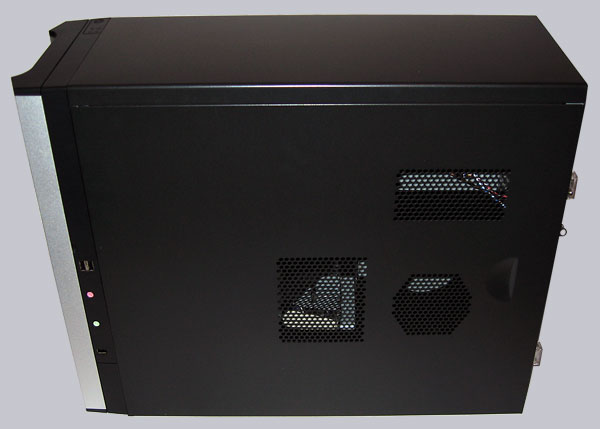
Thanks to the very good air flow it’s not problematic to have such a component arrangement. Here you see the removable side panel with some large fan grills in the right of the picture. In the left part of the picture, close to the front bazel one recognizes the well placed audio and USB connections.
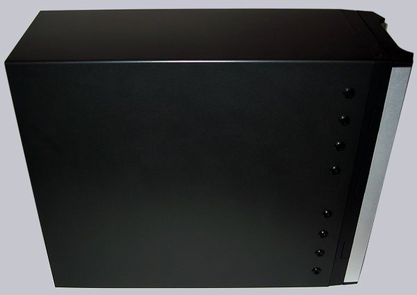
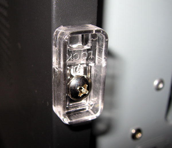
The other side panel is non-detachable and offers no way to take a motherboard tray out of the case, but due to the large work space inside of the case it’s nearly unnecessary to have a removable mainboard tray. And if you ask yourself, how to mount the screws for the 5.25 inch drive bays on this side, Sunbeamtech has a solution for us. The small black plastic caps close to the front have drill holes into the case, whereby one can mount the screws of each drive – nice idea and easy to handle.
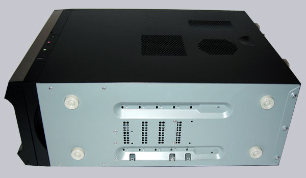
Now here is the bottom face of the case, where you see one big drawback of the Tuniq 2 Mid Tower. Because in the middle underside are the screw holes for the 4 hard disk drives, so you have to lay the case on one side to mount the screws and additionally the hot hard disks are nearly on the floor. It’s not really problematic on a parquet floor, but on carpeted floor this might be unfavorable during a longer period. A removable disk cage would have been clearly expedient. In order to prevent these problems, I would suggest to install all hard disk drives with 5.25 inch frames into the front 5.25″ bays.
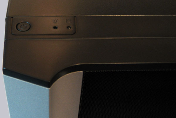
Here’s again a positive highlight of the Tuniq2 Mid Tower. Who was always annoyed at a badly accessible power button or activity LEDs, will love these control elements on the top of the case. The Reset button is still behind the front bazel, but who needs to Reset a well running PC every day ? 😉
Comfortable is also the mechanism to hold the side panel securely. It remains to be seen how long these small plastic clamps holds in the normal course of life, but the good case finish should promise a long life span.
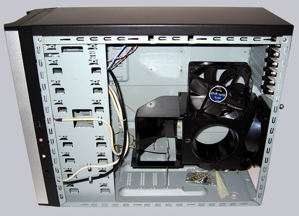
Let’s have a look inside of the Tuniq 2 chassis. All the edges are well folded and rounded. Before the installation of the motherboard one should take out the “Grand Fan Duct” (black plastic tube in the middle of the case) with both mounted 120 mm fans, which is no problem at all, because it’s only necessary to remove one screw and two small clamps to take it off. The fan duct helps to get fresh air for the CPU heatsink and the video card(s), so that the hardware with the most generation of heat stay very well cooled. In the bottom of the case you see once again the unfavourable placed hard drive cage, where the HDDs have to be mounted upright. The rest of the Tuniq 2 case is well thought out and offers very much space for the installation of all components.
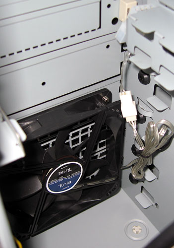
Here’s a picture of the 120mm fan which is already mounted in the lower front of the case. HDDs would be well cooled and best placed at this position.
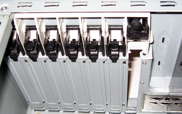
The installation of PCI, AGP and PCIe cards is thanks to the screw-free locking mechanism very easy.
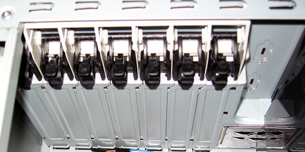
Simply lift up the small clamp as shown in the picture and take the card out – very fast and easy mechanism.
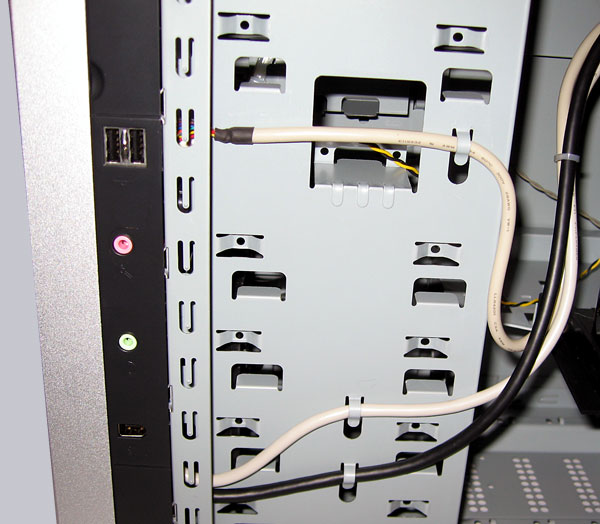
Very nice are these small retainers, which holds the IO cables perfectly.
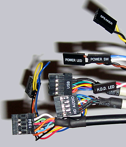
Here’s a picture of the well labeled front IO cables and the USB as well as audio plugs build in one block. So it’s not necessary to put as often usually each pin to the mainboard. Nevertheless I recommend to compare the pin allocation of the IEEE 1394, the USB and the audio plug with the mainboard manual before the first installation.
Result and general impression of the Sunbeamtech Tuniq 2 SB Case …