
Infrarot Repeater DIY Guide – self-made IR-Repeater Remote control HiFi equipment with the remote control through wall and cupboard
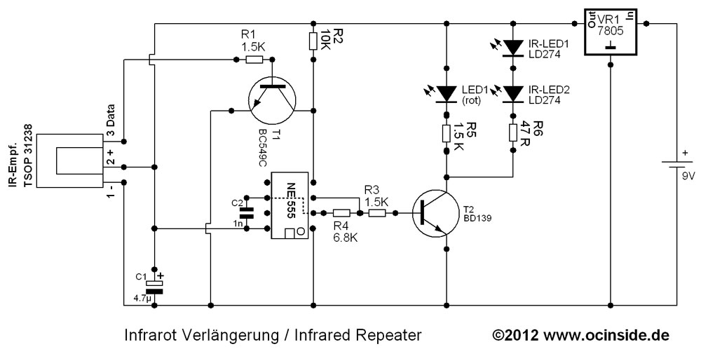
IR repeater function and circuit diagram of the IR repeater.
How the IR repeater works …
First, I would like to explain briefly here, how the IR-Repeater works.
When an infrared signal is received by the TSOP31238, it is routed to the BC 549C NPN transistor, which forwards the signal to the pin 4 (RST) of the NE 555 timer ICs, “waking it up” via reset and prompted an oscillating signal output at pin 3 (out). This signal is then transmitted with the powerful 139 BD NPN transistor to the transmitting diodes and parallel to a control LED with very low power consumption (low current). Since the modulation of the oscillator NE555 depends on various factors, for example on the input voltage, the circuit is powered by the positive voltage regulator 7805, which reduces the battery voltage constant at 5 volts.
The TSOP31238 is relatively insensitive to interference and works with many remotes, but it can still happen that the red LED flickers slightly and/or the device can not be operated. If the red LED flashes continuously, this could, for example, be triggered by a highfrequency light source e.g. of a fluorescent lamp or neon tube or the backlight of LCD TVs. It could help to cover the TSOP IR receiver a little bit or put it in a darker place/shadow. Or you can try a different position of the receiver device. Since the red low current LED indicates already the finest signals, a slight flickering of the LED must not necessarily interfere with the correct operation but it reduces the battery life slightly.
You could build the circuit with fewer components and remove the tantalum capacitor, or the voltage regulator and the transistor at the entrance of the NE-555 ICs, but the NE555 would oscillate continously without the transistor so it would emit signals continuously and consume more power. Without the voltage regulator and the capacitor a constant 5 volt power source is needed (regulated power supply).
Here is the diagram that I’ve designed for this IR repeater guide …
The components can be ordered as a kit in the Fanshop and can be combined e.g. with the USB Ultra IR v2.0 Kit.
The next page shows the soldering instructions of the IR repeater …