For the wiring of the display we first of all take the ribbon cable and solder it according to the following circuit diagram on the 25 pin sub-d (parallel port) plug, whereby in my small circuit diagram I described the rear side – consequently the solder side of the plug:
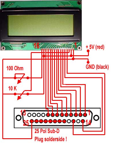
The pinlayout of the LCD display has to correspond to the following layout. Pin 15 und 16 will only be necessary for the background lighting, otherwise the wiring has to be adapted accordingly (in case of questions please don?t hesitate to ask me):
As first step I began with soldering the cable on the parallel port plug, thus I could be careful with the display as far as possible until I need it.
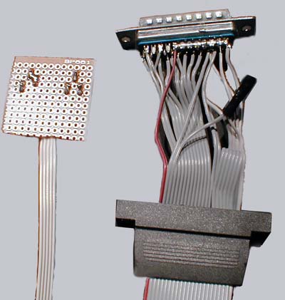
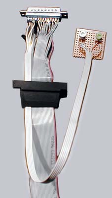
You should control the soldered positions several times and of course also pay your utmost attention to the circuit diagram!!! I soldered the small rotary poti for the brightness control of background lighting (100 Ohm) and the rotary poti for contrast control of the display on a PCB – but this is of course not imperatively neccessary. On the following pictures the LPT plug is already soldered on the ribbon cable:
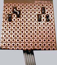
And here you can see once again the rear side of the small additional circuit board for the two potis:
During my first efforts I tried to receive the 5 Volt power supply over the printer port but this did not succeed really good. Therefore I finally decided to solder an additional 4 pin power supply cable (red and black) for the connection on the PC power supply.
If you have managed everything until now you have already the most difficult part behind you 😉
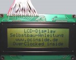
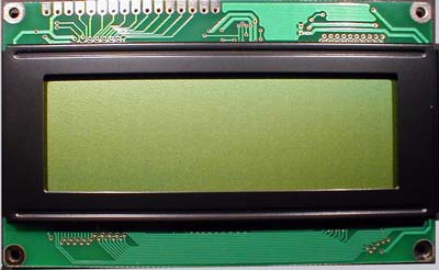
Now we can already unpack and examine the display.
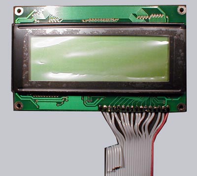
This is what the front cover looks like:
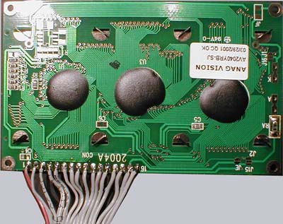
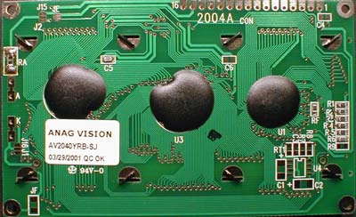
That is the rear side of the LCD display:
Now it is time for the easier part as we only have to solder the ribbon cable successively on the display. In order to get sufficient space for a further assembly on the front side of the LCD I recommend to solder the cables on the rear side, but this is up to your own decision.
If the wires have been ready soldered, the LCD side with the protective foil should look like this:
The rear side looks approximately like this: