

It’s very easy to increase the Vcore of the Elitegroup (ECS) Mainboards K7S6A, K7S5A, K7VZA and K7AMA by soldering just one resistor to the right point to allow your CPU much higher frequency. Of course it’s necessary to be very careful if you’re soldering something on your mainboard in order not to kill your board. And of course your warranty void if you solder anything on your mainboard !
Therefore i recommend a good grounding and a soldering station with seperate grounding !
But now let us do the Vcore mod …
On the upper called Elitegroup Mainboards are the Semiconductor KA7500B SMPS Controller as the voltage regulator, whereby of course it’s possible to mod this IC a little bit 😉
We just have to solder a resistor between Pin 1 and Pin 7 and fool so an incorrect voltage to cause a compensation of the Core voltage. In my tests i’ve used a normal 1/4 wattage resistor with 17 K.
Here you can see the positions where we have to solder the resistor to:
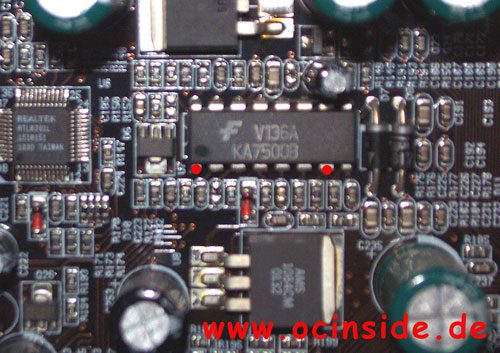
In the upper picture i’ve marked the soldering points with two red points.
You shouldn’t solder the resistor directly to the board in order to modify the resistance value once again. Just solder the resistor to a cable and then solder this cable to the marked pins.
After this modification you should check the correct position and check if there’s no tin at a wrong place !!!
Now put adhesive tape or a small piece of heat shrink sleeve over the resistor that it’s impossible to get a connection with the case or other components. After this small modification your Vcore should be 0,15 Volt higher than you’ve selected in your bios.
That means if you select a Vcore of 1,6 V the real ! Vcore is 1,75 Volt and with a selection of 1,75 V you’ll get 1,90 V Core voltage.
And if you set the voltage in your BIOS to 1,85 Volt or close the L7 (or L11) bridge, you’ll get a nice Vcore of 2,00 Volt. Whereby the voltage could diversify a little bit caused by the Power Supply Unit or by the used power transistors.
And if that’s still not enough for your CPU you could solder a smaller resistance value to the shown places, but the risk to destroy the processor is much higher, so keep watching the CPU temperature very well after each Vcore increasement !
I think that you also don’t like boring colour tables to find out the requested resistor colours for the desired Vcore, so i’ve made an interactive resistor where you can select the Vcore and get the right resistor value with the colours of this resistor 😉 The resistor tolerance is optional.
 |
 |
||||||||||
Or use a variable resistor with 50 K, solder it in a row to a 7 K resistor to prevent lower resistor values than 7 K and solder this to the two red points as shown in the picture above. Pay attention to the CPU temperature after increasing the Vcore !!! ! |


