
Step by step guide how to cut and paint the AMD Athlon XP, Morgan, T-Bred,etc bridges:
If you’ve already looked at the AMD Athlon XP Processor or at the XP painting guide, you’ve noticed that the OPGA (Organic Pin Grid Array) CPU isn’t a ceramic CPU.
Cut the bridges:
Because of the softer ground it’s much easier to cut these bridges and unlike the older ceramic CPU’s you don’t need to spend lot’s of time on this modification. Usually you can cut the bridges with a very sharp knife, but of course it’s also possible with a minidrill, dremel or with a thin stone disc bit of such a minidrill. About 0,5 – 1 mm is deep enough to cut a connected bridge and cut off the contact between the two golden points.
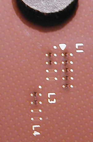
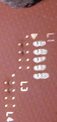
Here’s a picture of the five original lasercut L1 bridges and both lower connected L3 and L4 bridges:
Connect the bridges:
VERY IMPORTANT !!! DON’T CONNECT THE BRIDGES WITH SILVER LEADING VARNISH WITHOUT ISOLATION !!! Unlike the older ceramic processors the new Athlon XP CPUs have a copper plate below the bridges and you would connect the bridges to ground if you “fill” silver compound into this lasercut. The consequences would be that the CPU multiplier would set to limited values !!!
Method 1:
This easier and faster method is mentioned in our Forum
and doesn’t need insulation of the lacercuts 🙂
After you’ve cut and cleaned all necessary bridges carefully, you have to take a wire with lot’s of thin wires / laces inside (e.g. cable of a fan). Open this wire with a knife and take one of the small wires out of this cable. Now cut this thin wire into several about 4 mm short parts. Then take a pair of tweezers and dip one side into conductive silver compound, and hold this side to either point of the bridge you’d like to connect to untill it’s dryed (drying time about 20-30 seconds). Now put a little bit of silver compound to the other side of the wire, bend this wire to make a small bridge over the cut to the other point. That’s it ! But don’t use longer wire parts to prevent contact with the heatsink ! If you’ve the multi you like to reach it’s possible to insulate the wires with varnish.
Method 2:
Insulate (only) the lasercut by “filling” it with ceramic correction compound, silicon paste, etc.
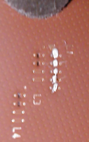
Here i’ve filled the five L1 lasercuts with ceramic varnish compound:
After “filling” the cuts you can wipe off the rest with benzine to get a plain surface.
If you’ve scrached into the surface while cutting the bridges insulate the scratches, too. Each scratch could be a ground !
Now it’s time to connect the bridges. A pencil doesn’t work really good, because the lasercuts are too deep 🙁 Or you try to paint around the cut, but if you watch the bridges with a magnifying glass you’ll notice that this couldn’t be a really good way… *LOL*
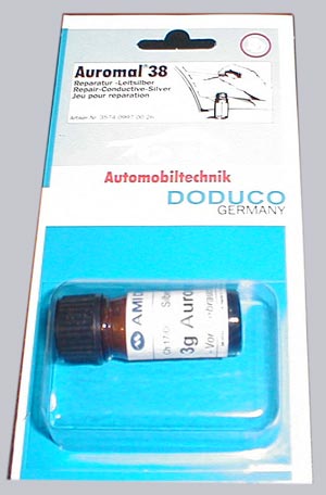
Therefore i’ll show you the better and more resistant way. A conductive pen for electronic circuits is very expensive (about 15 Euro), so go to a good car parts dealer and buy a “grid rear window defogger repair kit” 🙂
Here’s a picture of the small repair Kit bottle from a german dealer called A.T.U.
which costs about 9 Euro !!!
It’s very important that you clean the bridge points very carefully to get a good contact ! Now shake the bottle for a longer time to have enough silver particles in the emulsion. After this apply a small bridge between both points you’d like to connect with the point of a needle (nope, forget the big brush) and let it dry.
After the connection your bridge should look like this one:
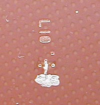
And here’s once again an example ! picture of the upper cut and insulated L10 bridge and a connected lower L10 bridge:
That’s it !
And if you get a wrong multiplier after the “painting”, just start at the beginning with well cleaned bridges ! After some tries you’ll get the necessary experiences. I know what i’m talking about because i’ve painted all !!! multi settings up to 18x of my interactive XP painting guide 😉
If you find an adhesive copper tape with a low resistance value on the lower side there’s no isolation necessary, i know such a copper tape to correct pcb lines, but i didn’t found a tape which is conductive at the adhesive side.
Close all L1 bridges if you want to change the multiplier via BIOS or Jumper. Otherway leave all L1 connections open.The multiplier settings by jumper or DIP-Switch doesn’t work on several boards, because they don’t “know” the newer multiplier IDs. That’s why i’ve created the new interactive XP painting guide 😉
Copyright by https://www.ocinside.de