USB Power cable connection for LC displays self-made
Succeeding the different solder instructions I would like to describe with the following little instruction how to use rather simple the 5 V power supply of an USB connection.
Sense of the USB power supply …
I received a lot of questions about how to move the power supply of LC displays to the outer part of the case. Here you have two possibilities: 1.) you could lead a 4-cable-plug of the main power source through a free slot shield out of the front side; 2.) simply follow this little instruction and solder your own adaptor, which uses the 5 V power supply of the USB port and supplies low power LCDs. Attention! The sum of power flow of all USB devices must not – under no circumstances – exceed 500 mA ! Thus, if there are already several USB devices in use, the main power device or a separate USB hub with an external power supply should be used. Now let us start with the main instruction, this time without the usual wiring diagram in order to make it really easy to understand and to build, even for beginners.
The following material is needed …
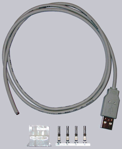
Let us first look to the necessary equipment, which can also be bought for little money as kit at the Overclocked inside Fanshop (at this time only within Europe):
1x USB A-Plug 1x 4-pin 5.25?? power plug 1x at least 2-cable shielded data cable of approx. 1 meter length (as long as needed) (second choice for this cable would be a commercial USB cable with USB A-connector like in the Fanshop kit)
Ready to begin …
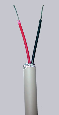
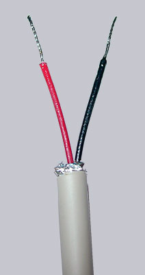
First of all cut approx. 2 cm of the outer Isolation of the USB cable and cut off nearly all other cables except the red and the black one (ground could be also soldered to the black cable, which is not really necessary here). After that the isolation of both cables have to be cut approx. 5 mm.
Sometimes USB cables have different colors. Here is a table with some possible USB cable colors (just in case your cable is NOT red, black, white and green):
These both cords are now ready to be tinned with a soldering iron by holding the iron at one side of the cord and pressing a bit soldering tin onto the other side…
Theses both tinned cable ends are now laid – as shown in the picture below – each in a single power slot to get soldered with a bit of soldering tin.
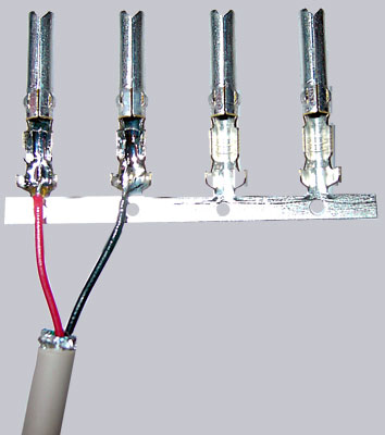
Now we pinch the holding plate off the two slots and tighten the cables´ clamps of the sockets (not really necessary, if soldered).
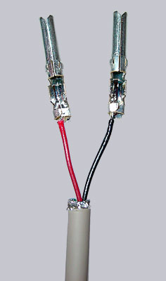
Then we lay the plastic socket with the slant side up and stick both finished cables as shown below (red left, black right next to it) into this plastic socket till we feel it fasten.
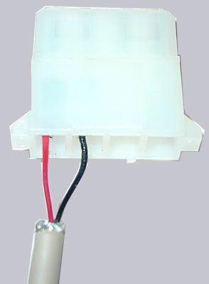
And that is the whole story. This time we don?t even need a shrinking tube, because the cables are properly tightened into the 4-pin power plug. Of course the two other sockets could be fixed with the plastic socket to be more stable, but since they are not used, each one of you can choose freely.
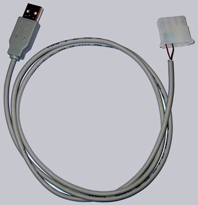
And that?s the look of the new self-made USB power cable, which could immediately be connected to the 4 pin power connector of the display PCB.