
Of course, the Vcore of the ENMIC 8KAX+ and the EPOX EP-8K7A mainboard can be increased about +0,4 Volt by the JP 2 Jumpers, but it’s never enough for hardcore overclocker 😉
But the more important option which is missing complete, is the increasement of VIO and VAGP. The VAGP is very useful for any higher graphiccard overclocking and the VIO helps you to reach better FSB overclocking results.
Of course it’s necessary to be very careful if you’re soldering something on your mainboard in order not to kill your board. And of course your warranty void if you solder anything on your mainboard !
Therefore i recommend a good grounding and a soldering station with seperate grounding !
So, now it’s time for the Vcore (CPU-voltage) solder guide .
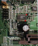
The Semtech SC 2422 is the well known voltage regulator of these boards (Biphase Current Mode Controller). This voltage regulator have a pin (FB/pin 7) for the voltage correction to allow manufacturers an optimal adaption of the Vcore and we can also use this pin to increase the vcore to “our correct Vcore” 🙂 Well, Epox and Enmic already connected this pin over jumper 2 with several resistor values up to 24 k to ground, but this is still not the end of the vcore. So it just make sense to solder another resistor from the FB pin to ground if you like to get more than +0,4 Volt.
I’ve written a small script to calculate the right resistor value for the desired Vcore:
My CPU should get Volt more
On this picture you can easy locate the positions of the two soldering points:
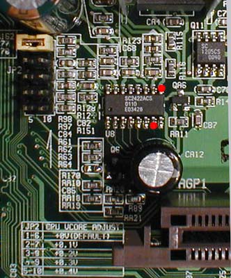
In the enlargement i’ve marked the two easiest positions with red points. I didn’t solder the resistor directly to the board in order to modify the resistance value once again. Just solder the resistor to a cable and then solder this cable to the marked pins.
After this modification you should check the correct position and don’t pull the soldered wire !!! Now put adhesive tape or a small piece of heat shrink sleeve over the resistor that it’s impossible to get a connection with other components.
From now on your board will have the increasement you’ve chosen in the upper script 🙂
Pay attention to the CPU temperature after increasing the Vcore !!!
Now it’s time for the VIO and VAGP solder guide:
On both boards the UNISEM US-3034 (8-pin PWM Switcher Controller) is used for the voltage of 3,3 V which is located near by the DDR-memory sockets. This SMD IC isn’t very big, i know, therefore you shouldn’t solder this IC if you’ve no good experiences in soldering such small parts. If you like to get more solder experience, take an older (e.g. unused CDROM) PCB and try to de-solder and solder several resistors, capacitors, etc. I’m sure you’ll notice when you’re ready to solder something on your mainboard 😉
This UNISEM VR have a VFB pin (pin 3) for error correction which we can use to correct it to the wished VIO (Voltage Input/Output) if we connect this pin with a resistor to ground (e.g. Pin 5).
It’s possible to increase the VIO up to 4 Volt or more without any bigger problems, but i think 3,6 Volt is enough for most FSB rates. Above this value it’s necessary to cool several ICs.
Just solder a normal 6,2 K (1/4 Watt) resistor to the two red points in the following picture to get 3,6 Volt VIO (a plus of 0,2 Volt):
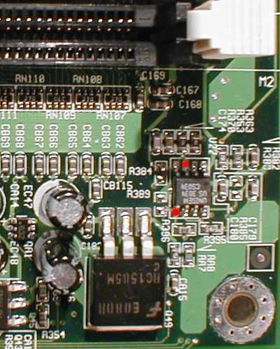
I prefer to solder the resistor over a cable to these points to change the resistor without soldering this IC once again.
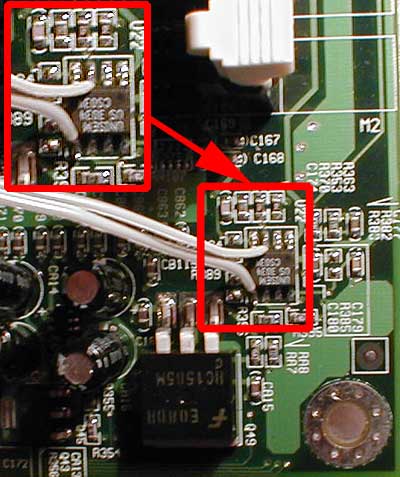
Here you see a picture of the already soldered cable for the 6,2 K resistor:
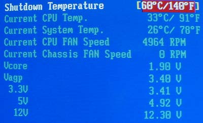
If you took a look into the PC-Health Menu of the BIOS before the modification you’ll know this picture:
But these times are gone from now on 🙂 because after the mod your PC-Health Menu should look like this picture:
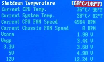
I think this is a reason to be happy and it’s also a reason to get higher oc results with an increasement of 0,2 Volt VIO and an increasement of 0,04 Volt VAGP for higher graphiccard results.
As i mentioned before, it’s possible to get much higher IO and AGP voltage with lower resistor values, but think about a very good case and IC cooling !!!
Once again many thanks to ENMIC for their testboard !
!