
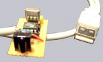
Self-made USB infrared receiver to remote control your PC
Succeeding the infrared receiver for the serial port I would like to present to you a very special instruction, which leads you to possession of an IR receiver fro the USB port.
USB is unfortunately a bit more complicated than serial …
Admittedly it is not as easy as the use of the serial port, because the USB port needs special drivers to run. Thus we need some kind of firmware, which directly leads to the need of something to record and process this firmware.
I decided to take the very small Atmel AT90S2323-10 PI IC, which – with its 8 pins – shows performance bordering on the miraculous. In this very chip there is a small 8 bit AVR RISC processor with 2 KB Flash ROM, 128 byte internal memory, 128 byte programmable EEPROM, timer and so on? and this little dwarf at any rate shows calculation performance of 10 MIPS headed by a 10 MHz quartz. But since we are at ocinside.de no processor may get off without being slightly overclocked. Thus it is going to be used with a 12 MHz quartz 🙂 to process signals faster.
To spare ourselves the trouble of programming and building the programmer for the parallel port, I offer to you the Atmel IC as a complete kit in the fanshop completely programmed !!! Anyone who likes to purchase the necessary components somewhere else can of course program the IC by her/himself e.g. via PonyProg
where you can also find some circuits for constructing a prommer. BTW: firmware and drivers derive from an ingenious programmer named Igor
living in the Slowakei to whom I am very grateful for his first-class work !
The necessary components …
Now it is time to get to the necessary components, also available – as mentioned shortly above – as complete kit in the fanshop with already programmed Atmel IC:
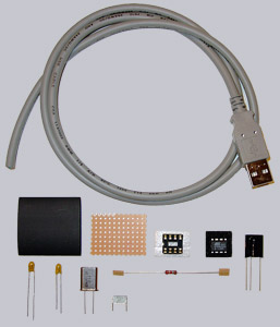
1x Vishay TSOP 1738 (38 kHz infrared receiver) Comparable to this are also: Vishay TSOP 1838, Vishay TSOP 11xx, Siemens SFH 506, or Siemens SFH 5110 ! Attention ! the pin layouts of those compared types are not the same of necessity as the ones used in the TSOP 1738 circuit; refer to the manual of the chosen IR receiver!
1x Atmel AT90S2323-10 1x 8-pin IC-Socket 1x 12MHz quartz 1x 4.7µF / 16 volt capacitor (Elko or Tantal) vertical construction 1x 10µF / 16 volt capacitor (Elko or Tantal) vertical construction 1x 100nF capacitor (ceramik, layer or multilayer) vertical construction 1x 1.5 K resistance
(0,25 watt) 1x Printed circuit board (PCB); approx. 5 cm² is sufficient 1x USB A-plug male 1x approx. 1 meter shielded data cabel at least 4 pin (As one chooses a finished USB cabel with A plug can be used as describes in the fanshop kit) A piece of shrink tube (if you want the PCB to be isolated)