
Infrarot Repeater DIY Guide – self-made IR-Repeater Remote control HiFi equipment with the remote control through wall and cupboard
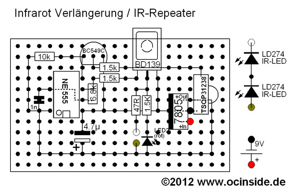
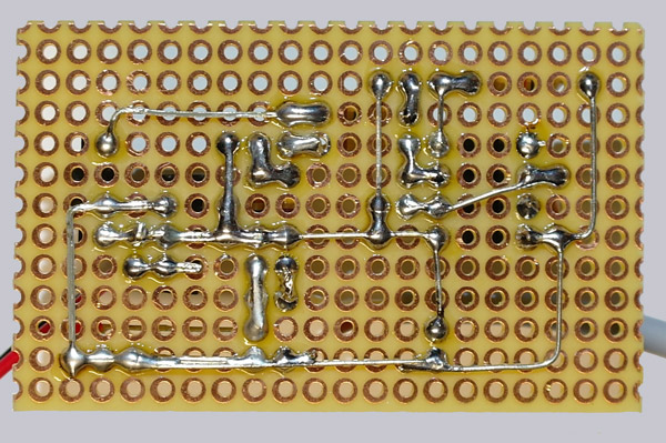
The board layout of the IR Extender
Enough theory, let’s come to the practice …
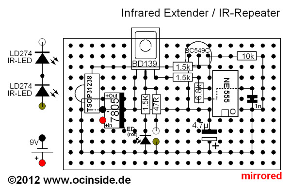
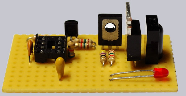
Here is first, for easy rework, a representation of the PCB with all components and connections that you can examine, during your soldering iron (15 – 25 Watt) heats up:
The right way of fitting the components …
First, we begin to put the parts in place, as shown, on the 20 x 12 holes of the breadboard. For a better support the respective pins can be bent slightly below the board. But please for now DO NOT cut the pins !!! It is important that the small notch of the IC socket and, later, the IC faces downward. The small transistor BC 549C is mounted with the flat side down, the greater BD 139 with the metal surface downwards and the 7805 voltage regulator must be mounted with the metal surface to the left. For the LED you also have to ensure the correct polarity. As you can see, the polarity of the two LEDs is shown simultaneously on one screen. Furthermore, you have to pay attention to the correct polarity of 4.7 uF tantalum capacitor (small yellow one), where the positive pole also has to point down! Next to the “16” there is a small plus (+) mark on the component which has to face away from the base. For the other components, there is no polarity needed , so that there is only the proper position important.
Here is a picture of the various tantalum capacitor designs and the polarity:
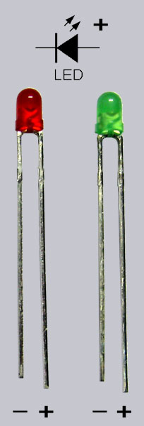
And here’s a picture of the LED polarity, the shorter leg with larger bonding surface and the reflector within the light emitting diode cathode / GND / ground / – / VSS. The longer pin with the smaller joint surface within the light-emitting diode is the anode / + / VCC:
In this Video Mike shows his IR-Repeater PCB assembly and some solder points.
Note: Please allow our cookies first to see this external content!
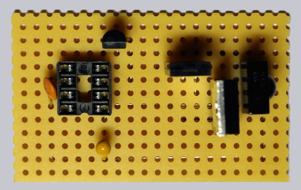
This is a photo from the upper side of the first step:
If all parts are plugged as shown and are a little bit fixed, we you can continue with the bottom. So for you do not always have to turn the board to locate the components, I also have created a mirror image of the board for better orientation.
Here is the mirror-inverted image for better orientation at the bottom …
The proper bending and pinching the pins …
Now you should, just based on the photos, turn all the pins of the components and cut them, but make 100% sure that all components are in the correct position as explained above and you took care of the correct polarity. If you make a mistake at this point, it is pretty hard to fix it later and all the work was maybe for nothing. So take your time to bend everything 100% exact and cut the pins off at the right length. You should use pointed-nose pliers and a wire cutter, then it should be no problem.
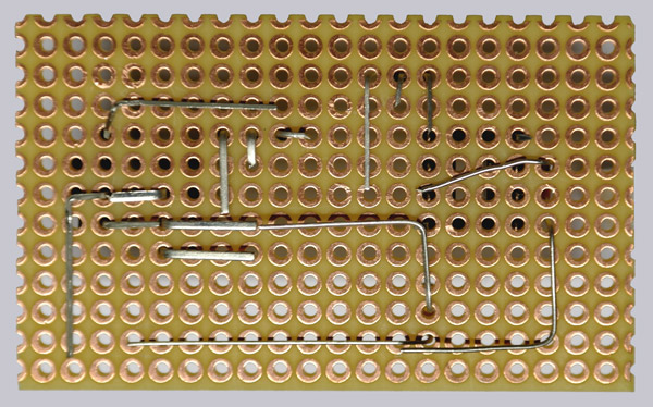
So that’s how the bottom looks in the first step after bending and pinching the pins:
Let us continue with the next components that are attached as shown:
The 6.8K resistor close to the IC socket needs to be vertically inserted in the PCB, by bending one leg 180 ° and plug the resistor into the board. As mentioned above, care must be taken to the correct polarity of the LED to make them work right. The red LED is plugged in near the 1.5K resistor, that the shorter pin (-) points to the resistor and the longer pin (+) points to the lower long connection.
If you want to order the IR-Repeater Box from the Fanshop, you might want to see every incoming signal. This can only be dond if the legs of the LED are left very long, so that the LED eg afterwards should be seen on the top of the box. From the top of the board to the top of the IR repeater box is about 21 mm, so you should put the LED into the board until the longer legs look out of surface about 10mm. Alternatively, you can bend it, as shown above, to the front.
If you dont want to use the box, the LED can be connected directly to the motherboard or folded forward. And if you want to install the entire board somewhere, you can of course also solder a 2-pin cable to accommodate the LED, for example, in a larger box.
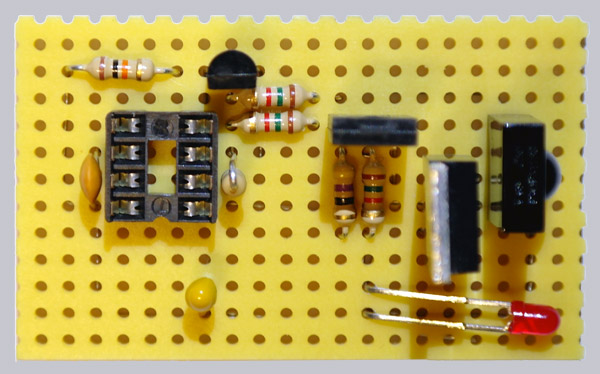
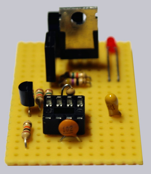
Here is again the top of the board in another angle:
That is the top of the board from the left side:
So the bottom looks like this after the second step and after the bending and pinching the pins:
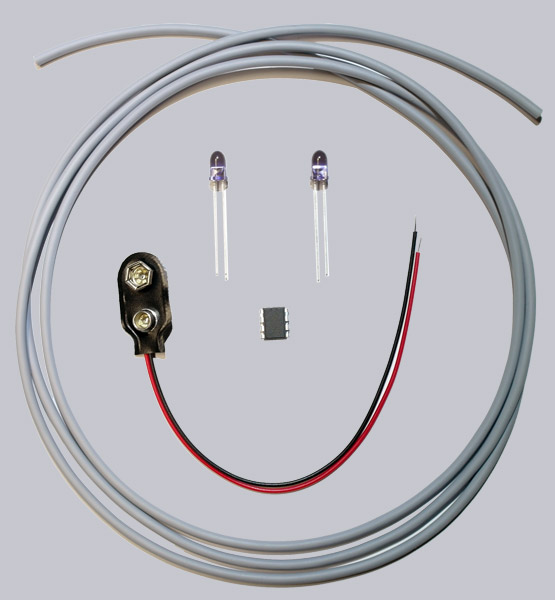
If nothing was forgotten until now should have the following items left which we mount later.
Exactly these components are left so far:
First, only the pins of the components shown should be soldered …
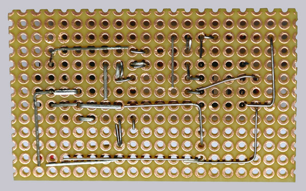
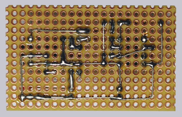
We now first solder all pins on the bottom of the board as shown in the following image. Please do not solder more, but only the shown, since we are inserting the cables right away. Please pay attention to the free spaces and that there is no connection there !!!
That’s how the bottom side should look like at this point:
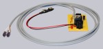
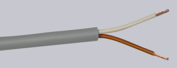
So, the cable is prepared on both sides …
At first dismantle the cable:
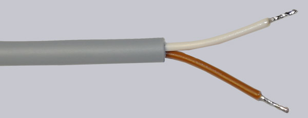
After that, put some soldering tin at the open ends:
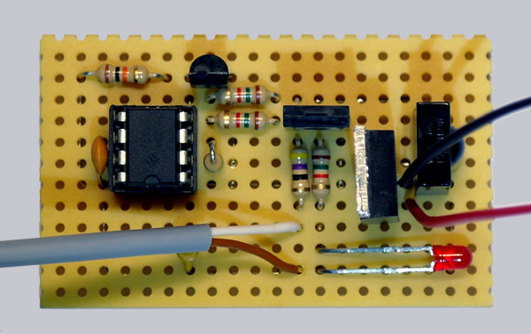
Put the cable into the correct position on the PCB …
The white wire of the 150 cm long cable is plugged to the 47 ohm resistor and the brown wire is connected to the lower long connection. Then the black cable of the 9 V battery clip is connected between the voltage regulator 7805 (the lower pin) and the TSOP IR receiver(the middle Pin). The red wire from the battery clip is connected at the bottom to the completely free pin of the 7805 voltage regulator.
Solder the remaining connections …
Now we solder, as shown, the remaining bridges. But look carefully at the free spaces (e.g. do NOT solder the two pins from the capacitor or the LED together). The brown and white wires of the 150 cm long cable we now solder to the pins 4 & 5 from the optocoupler (on the next picture below left), which is led later to the PC’s power button.
Here is a picture of the finished soldered board bottom:
Infrared LEDs soldered …
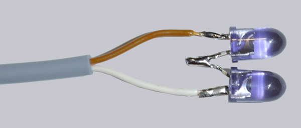
The two IR transmitting LED’s can be easily soldered with long and short legs together so that the two LEDs are connected in series (positive pole to the negative pole of the other LED). Who wants to, can solder the two IR LEDs each to a separate cable, and then turn the two cables as described above for the two LEDs in series, but of course obey also the correct polarity.
The two infrared LEDs are soldered together at the brown and white wires:
Den IC richtig einsetzen …
Now insert the IC with the notch (or point) fitting the notch of the IC Socket (in the picture below ie to the right).
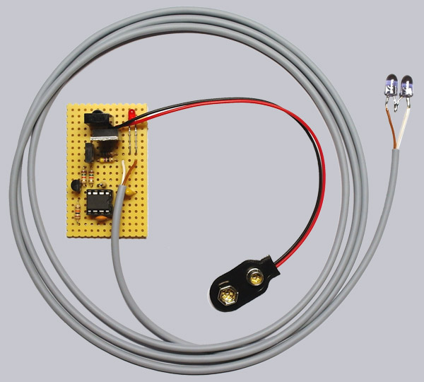
The infrared repeater is ready … 🙂

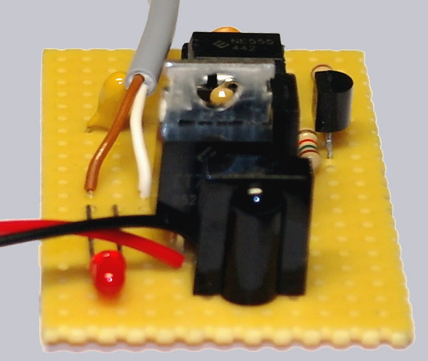
Here again is a close up of the finished board:
In this Video you’ll see again the soldered IR-Repeater.
Note: Please allow our cookies first to see this external content!
The best way is to check now again all solder joints and the polarity of all components and cables. Although it is now already pretty late to discover mistakes, but better late than never and there can never be enough control. If you notice an error yet, and this is not so easy to solve, feel free to contact me and I’m glad to help you by mail or in our forums.
Continue with the operation of the IR repeater …