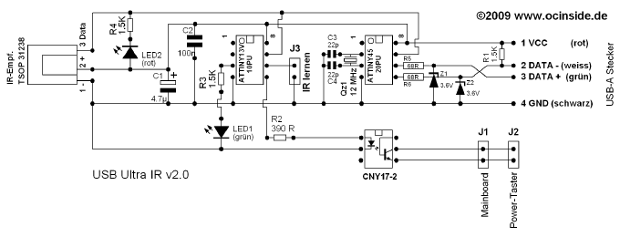
The function and the circuit diagram of the USB Ultra IR receiver v2.0
The USB Ultra IR receiver v2.0 functions …
First I would like to explain here briefly, what the USB Ultra IR v2.0 receiver makes at all.
When the TSOP31238 receives a RC5 coded infrared signal, it gets on the one hand directly to pin 7 of the programmable ATtiny45-20PU Atmel IC.
This Atmel IC, is clocked in the circuit with a 12 MHz quartz and provides a communication between the Infrared receiver and the PC, so that this signal can being processed by infrared receiver programs like Girder.
The 1.5 K resistor is as Pullup resistor between the negative data line and the 5 V power supply of the USB connetor to stabilize the logical signal.
The two 3V6 Zener diodes with the 68 ohm resistors limit the voltage at both USB data lines Data+ and DATA-, so that they finally only get approx. 3.3 V instead of 5 V from the Atmel IC.
Further a red low-current (power saving) control LED is soldered with a 1.5K resistor between DATA (Pin3) and +5 V VCC (Pin2) of the TSOP infrared sensor.
The signal goes however not only to the PC, but also to the second ATtiny13V-10PU Atmel IC, which have to be programmed with a special firmware before and has the following function:
– If the Jumper J3 is put in, the AVR IC save the valid RC5 code of an infrared remote control in the integrated EEPROM to compare it. The desired key on the remote control for switching on and switching off the PC is thus programmed. As soon as a valid RC5 signal of the remote control arrives, a green low current LED with a 1.5K resistance and the opto coupler with a 390 ohm resistor is supplied with power.
– When the Jumper is then taken off, the small 8-bits AVR RISC processor compares all incoming signals with the stored signal of the EEPROM and if the two signals are equal, the opto coupler is supplied with power.
Unfortunately the ATTINY13V-10PU Atmel IC cannot be programmed any longer as simply as the AT90S2323 IC in the USB infrared receiver guidance, since Atmel changed some special Fuse bits which prevents a programming of the firmware with conventional ISP prommer (ISP = in system prommer). For this reason I program the firmware with a more complex Atmel programmer directly on the ICs and offer them programmed as kit in the Fanshop. Here I set also all fuse bits that this Atmel IC needs no external quartz or resonator.
The opto-coupler and the solution to switch the PC on and off …
After careful consideration and numerous tests I decided to pass the switching signal of the Atmel IC over a 390 ohms resistor to an opto coupler, which has the task, to connect its 2-pole output (pin 4 & pin 5), as soon as the input pins (pin 1 & pin 2) got the switching voltage. This output could be connected e.g. with a WoL (Wake on Lan) connector, where we can also get the 5 Volt power. However, then one would not have the ingenious advantage to additionally switch its PC off.
For this reason I decided for better solution, where the output of the opto coupler is connected directly with the PC power Button parallel to the power Button connection of the motherboard. The circuit get its necessary 5 V power supply over an USB cable, because current ATX Mainboards supplies the USB port also with power when the PC is switched off if this is activated by a Jumper (+5VSB) or in the BIOS. If this is not the case, or the PC has no necessary PowerOn feature, it’s possible to get the 5 Volt power over a small external 5 Volt regulated power supply unit. To separate the 5 V USB power supply you could cut, for example, the VCC connection from Pin8 of the ATTINY45 to Pin8 of the ATTINY13V or connect the complete circuit simply to an active USB Hub with external power supply to supply the circuit continuously with power. Alternatively it would be possible to get it from the ATX power supply connector directly. However a wrong wiring would forgive no errors, therefore I would not like to continue here with a detailed explanation. A PC ATX PSU pinout can be found in our Forum – e.g. in this PC power supply pinout topic.
It’s easy to check if the USB port gets power when the PC is switched off, with an optical Mouse at the USB port. Because the lighting of the optical scanning continues in this case if the PC is switched off. Of course it’s also possible to measure the voltage of the USB port. And who would like to vary a little bit, can use the WoL connection of the Mainboard.
Here is the circuit for the USB Ultra IR v2.0 guide …
Here is the connection diagram of the old USB Ultra IR v1.1.
Additionally I have also build another variant for the operation of the power AND the reset button. Here is a link to the special POWER and RESET circuit. If you would like to build this, you can order e.g. the USB Ultra IR v2.0 kit in combination with the normal Ultra IR kit and develop hereby the special reset & power circuit.


