
Practical testing …
The WLAN ESP8266 module has been tested on the following system:
PC:
Intel Core i7 6700K @ 4 GHz
4x 4 GB DDR4 RAM
ASRock Z170 Extreme6+
Asus Strix Nvidia GeForce 980ti
Seasonic Platinum power supply 760W
Samsung Pro 840 Pro 256 GB SSD
CM Storm Stryker case
OS & Software:
Windows 10 Professional 64 Bit
Arduino IDE Version 1.8.2
ESPlorer v0.2.0 rc5
Blynk Software 2.13.0 (Blynk website)
In the following chapter we would like to show you how to use the ESP8266 and the software “Blynk” to switch a channel and thus control domestic devices. The procedure is divided into three stations: the server, the mobile device and of course the ESP8266 itself. Let’s start with the server.
The Blynk server …
The following software can be installed and run on a Raspberry Pi, Windows or Mac and even on a NAS. A current Java version is required. Afterwards you can download the server from the Blynk website and save it to a folder named Blynk.
Blynk Server Download
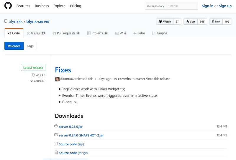
Our version is the server-0.23.5.5.jar. We now start it in the folder with the following command:
java -jar server-0.23.5.jar -dataFolder C:\Blynk
As confirmation we only receive the following message.

This would make the server ready for use. Let us now move on to the mobile device.
The mobile device …
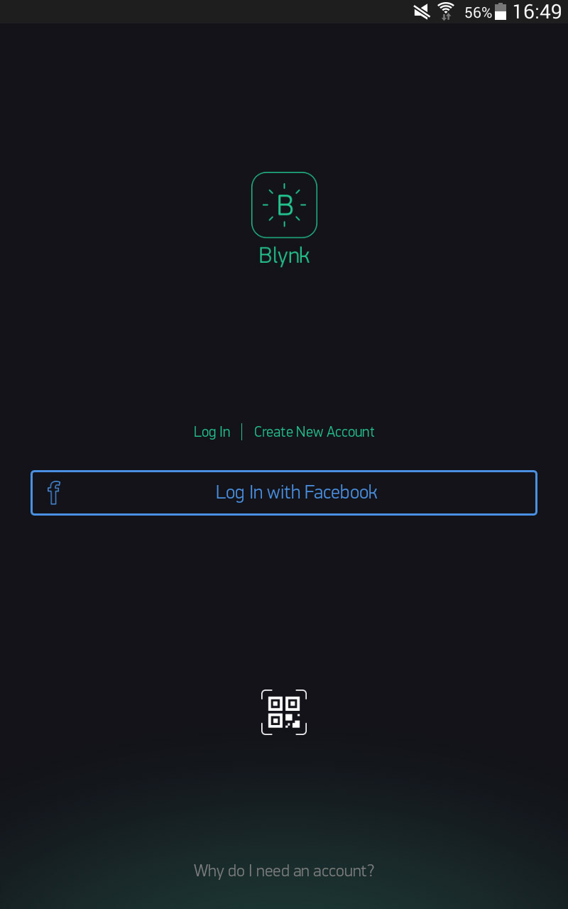
We install the Blynk App, in our case from the Google Play Store. The following screen will then be presented to us, where we select the “Log In” option. The account data is “admin@blynk.cc” and the password is “admin”.
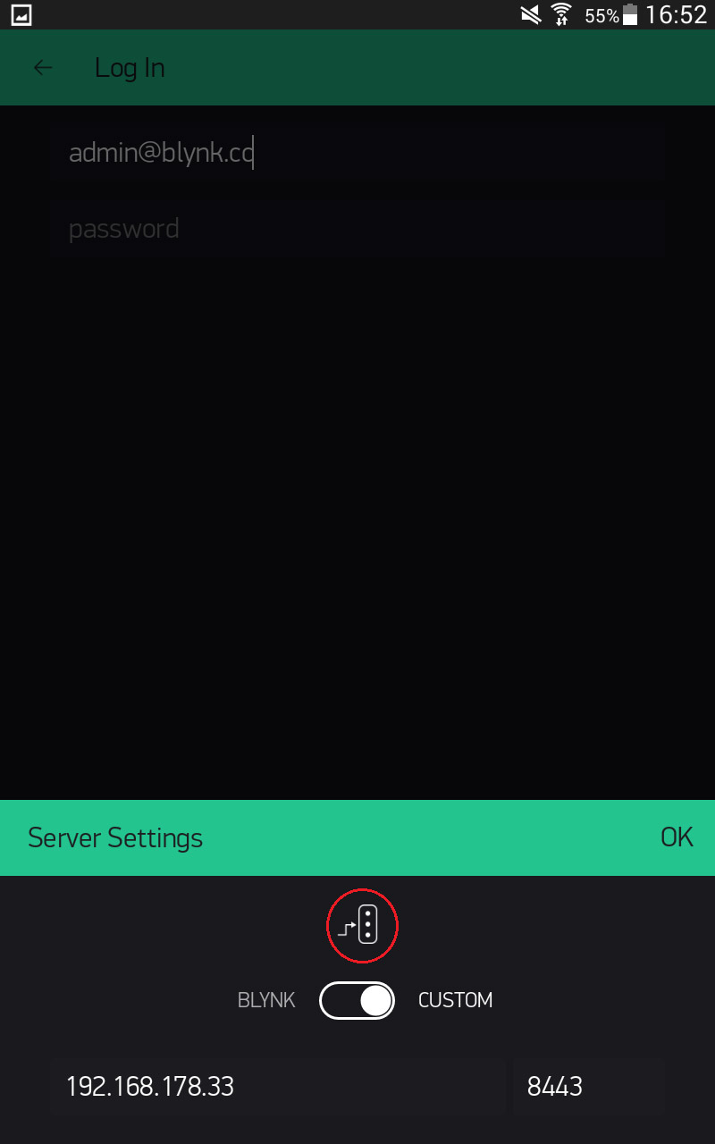
But before we click on Log In, we select the small icon at the bottom, move the slider to “Custom” and enter our server IP. The port remains unchanged. We confirm with “OK” and log in.
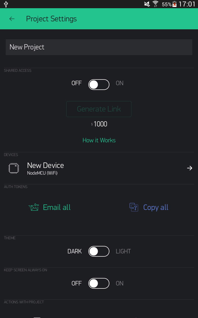
The following screen appears. A click on the small hexagon nut in the upper right corner allows us to make the settings.
In the point “New Device” we select our NodeMCU as the chip with a WiFi connection.
The next step is the setup of the ESP module.
The ESP8266 module …
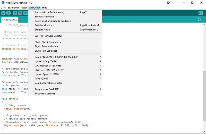
The configuration is also very simple. We restart our well-known Arduino software and select File under Examples, Blynk, Boards_WiFi the NodeMCU module. A template sketch is loaded that looks like this:
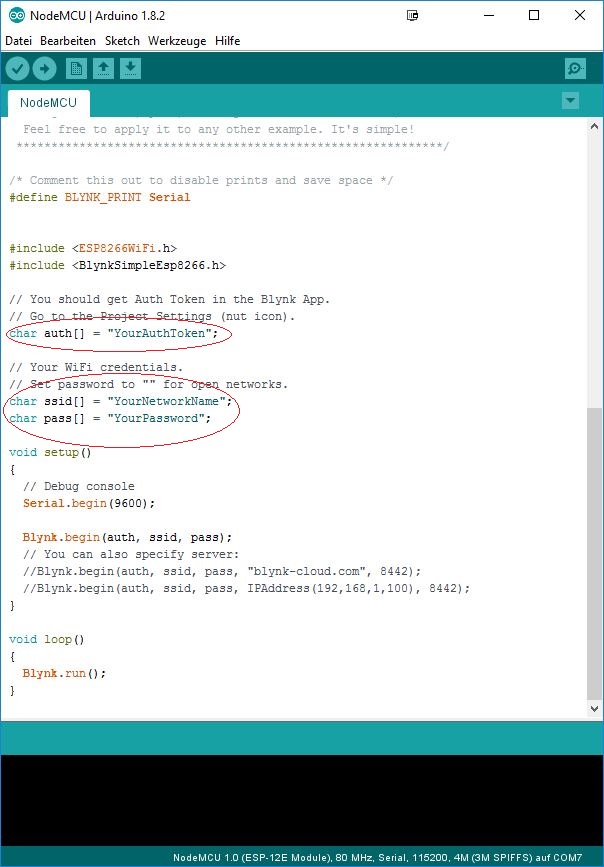
We now have to make the following changes.
char auth[] = “YourAuthToken”;
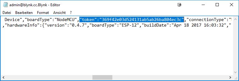
In the field “YourAuthToken” the token from the configuration file of the server must be entered. The configuration file is located in our Blynk folder and was created with the admin login. Here we copy the following entry and enter it in the above-mentioned field.
char ssid[] = “YourNetworkName”;
The SSID of the WLAN network to which the ESP8266 should connect must be entered in the field “YourNetworkName”.
char pass[] = “YourPassword”;
The WLAN password is entered in this field. The quotation marks must remain on each entry. You also have to make a change in the lower part of the file.

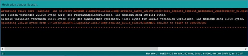
The top line must be commented out and the IP address of the computer on which the Blynk server is currently running must be entered in the IP address field. Afterwards we upload the whole sketch with the following settings to the ESP.
If the transmission is successful, we will receive the following message:
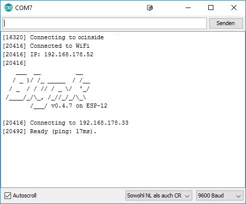
From now on, the module has a local baud rate of 9600, so if you set it in the serial monitor in the Arduino Tool, we see the following display after pressing the reset button, which confirms that the system is ready to run.
This would be the most difficult part of the tutorial.
Now we connect an LED for testing and set this in our Blynk software. For this purpose we connect the channels D0, D1 and D2 with …
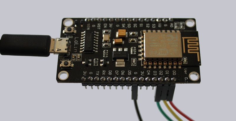
… the anode (+) of the light emitting diodes. Which are then collected at the cathodes and fed back to a G (GND, ground) connection of the ESP module.
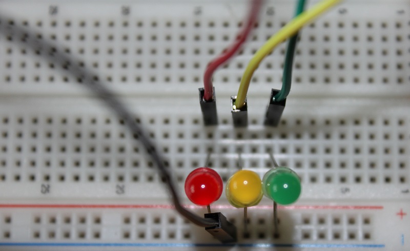
At this point it should be noted that only light emitting diodes with an operating voltage of 3.3 V can be connected directly. If diodes with a lower voltage are to be applied, a series resistor is required. How to calculate this is explained by numerous resistance calculators in the network and the LED FAQ in our forum.
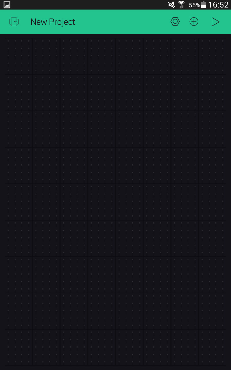
Afterwards we start our Blynk software again and add a button on the project screen with the plus symbol.
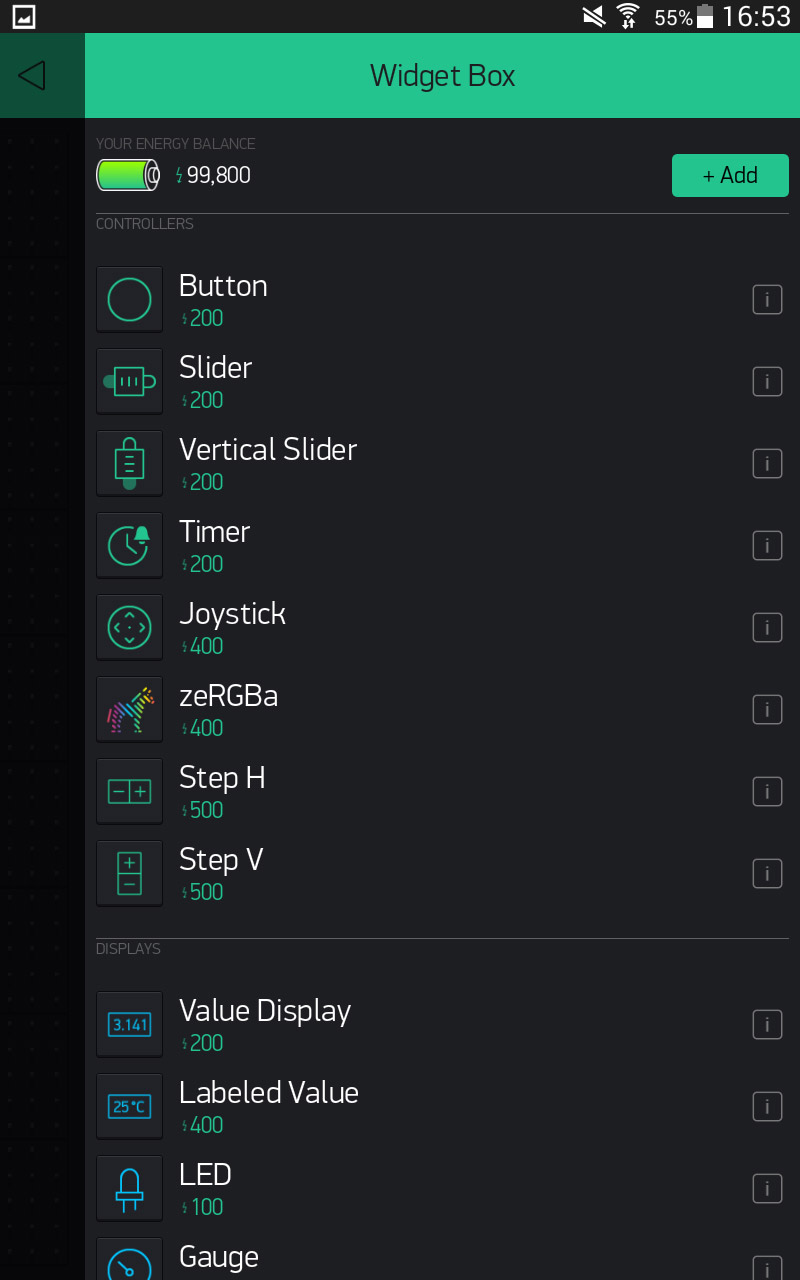
A click on the button opens the options of the button. There we can enter a description and select the channel on the ESP. In our case we call it “Led red” and assign the channel “D0” to it. If you hold down the button in the project screen you can change its position on the screen. In the same way we can now add the two other buttons.
If we have done everything right, the project should look something like this and run the channels D0, D1 and D2.
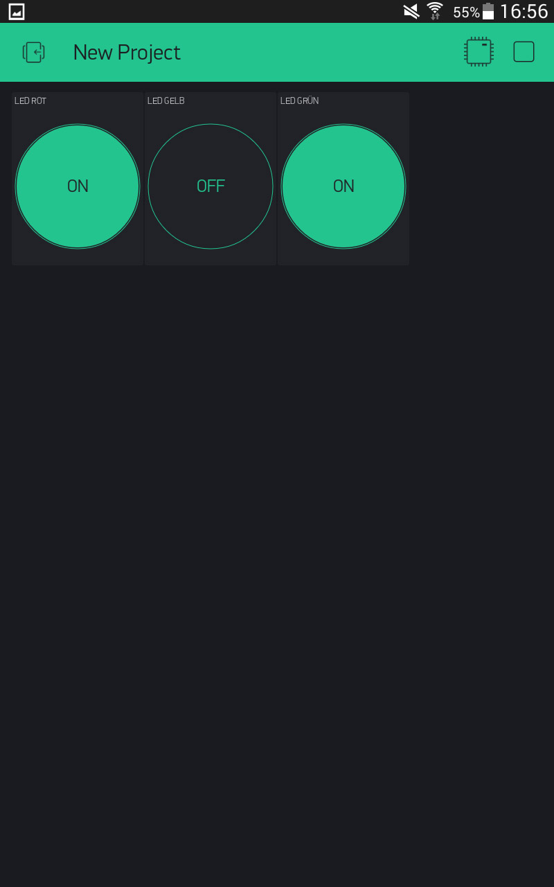
Pressing the Play icon in the upper right corner of the screen should turn on the LEDs after pressing the respective button.
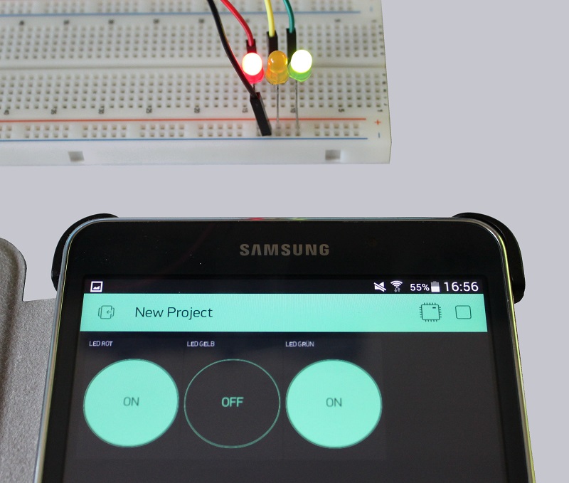
We did it!
Now you can adjust the circuit individually to your needs. For example, a 3.3 V power source can be connected to pins “3V” and “G”. You can also use a USB battery for mobile applications. The LEDs can be replaced by small transistor circuits including relays to switch larger loads. The possibilities are huge!
Annotations …
Normally, the Blynk software is not a classic free software. The sensors, buttons and modules must be “bought” with energy. If the start energy of 1000 is empty, new energy must be bought with real money. However, the project is also accessible from the Internet via the Blynk platform. The contribution understands itself as “server rent”.
The setup of a local server avoids this problem completely legally by hosting the whole thing at home and therefore no costs for the operator. Of course, it is also possible to reach your server from outside via VPN/DNS.;) That would also clarify the aspect of security. Let’s now come to the conclusion about the WLAN ESP8266 module.
WLAN ESP8266 module Conclusion and overall impression …