

Step stick swap, install silent stepper motor driver …
3D printers are controlled by so-called stepper motors, which, as the name suggests, always move in small but fixed steps and can be held at this position. Usually four lines are needed for the two phases of the bipolar stepper motors. To control the stepper motors (steppers) ICs are needed, which are called stepper drivers or StepStick.
Anyone using their 3D printer for the first time will be surprised at the whistling sounds and similar tones up to a melody.
A special feature of the stepper motors is that they start to sing, whistle, etc., depending on the StepStick and the voltage set by holding their position. Now it is also the case that the StepSticks can control the stepper motors not only in whole steps, but moreover in microsteps, which means that the stepper motors can move in many, very fine steps (TMC2208 V3.0 StepSticks offer e.g. 256 microsteps per full step!) and can therefore move much more precisely and above all also more quietly. That’s why they are also called SilentStepSticks.
That means: Without any new stepper motors the 3D printer runs quieter and more precise and power saving with better StepSticks than with the old stepper drivers (e.g. Pololu A4988).
Why don’t some manufacturers install better drivers directly? Quite simply, for cost reasons, because five A4988 cost, for example, for end customers in the trade about 8 euros and the five TMC2208 V3.0 drivers used here from PoPprint or MKS or Bigtreetech currently cost about 20 euros or Kingprint TMC2209 V1.2 are about 35 euros! So 3D printer manufacturers can save a lot of money on such products, just as they do on fans in production. Money that we invest but now again 😀
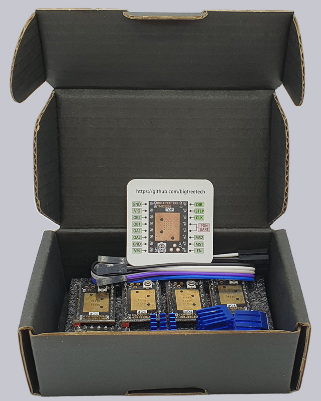
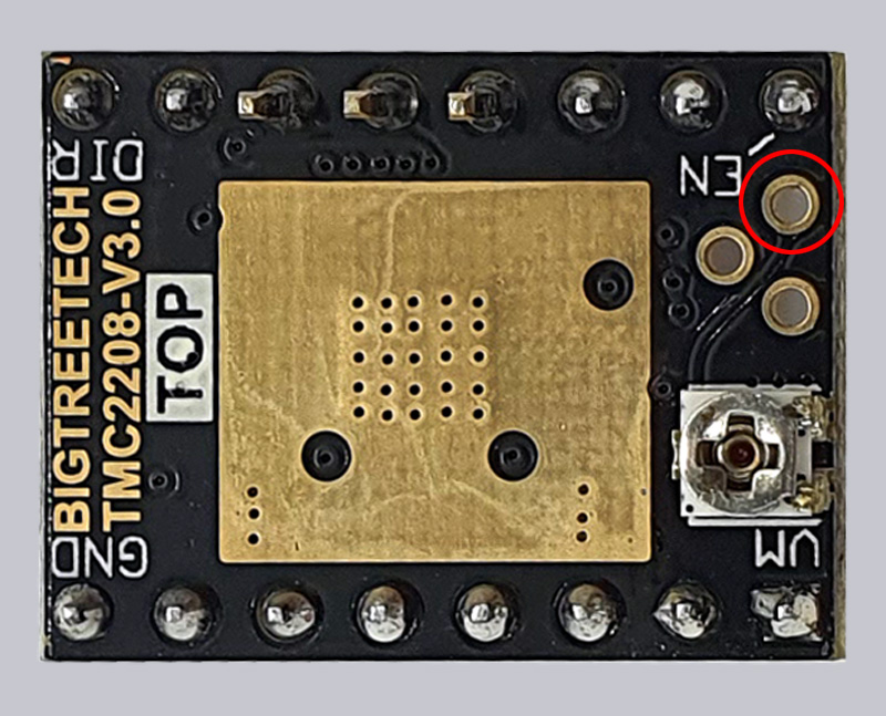
Here you can see the five new TMC2208 V3.0 StepSticks with pinout.
There are some more points, which would go into too much detail at this point, but at least you should know that a Trinamic TMC2208 V3.0 StepStick can be controlled via UART and then also dynamically switch between spreadCycle and for a smoother positioning via stealthChop2 (via Active STEP/DIR or via OTP bits in Standalone Mode One Time Programmable only 1x writable). TMC2209 also support Sensorless Homing.
The voltage of the stepper motors also plays a major role and is set via a small potentiometer on the StepStick or can be adjusted in UART mode via M906 GCode.
Let’s start now with the stepper motor driver swap …
At this point we will show the easiest way to replace the StepStick with a new one, set the voltage and adjust the firmware to avoid changing the pinout of the stepper motor phases. This is because when swapping from A4988 to TMC2208, you would actually have to change the polarity of the wires (see 3D Printer Conversion Guide).
3D printer cover removal …
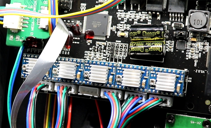
To do this, we need to unplug the 3D printer again and remove the bottom cover (as described on the previous fan replacement page) to access the motherboard – in our case a Trigorilla 0.0.2 motherboard, which was installed in the Anycubic Mega S until mid-2020.

Important note! Never disconnect or connect the plugs of the stepper motors during operation! The load change could destroy the drivers and more!
3D Printer Labeling Cables …
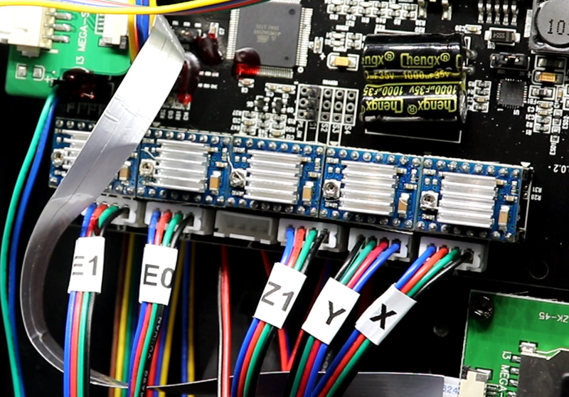
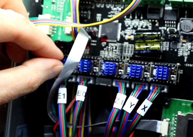
Now we first attach small stickers to the respective supply lines (or write them with a permanent marker on the cables), so that we can control all stepper motors with the correct driver again afterwards and not mix up the axes by mistake. E1 is the second Z axis, E0 is the extruder, then Z1 and Y and on the far right the X axis.
3D Printer StepStick measure …
Now we disconnect these five plugs, switch on the printer with the disconnected plugs and can (if we like) times measure the set voltage of the currently installed A4988 StepStick. However, this step is not absolutely necessary. We measured the following values: E1: 0.9V, E0: 0.77V, Z: 0.9V, Y: 1.0V, X: 0.9V
Replace the 3D printer StepStick …
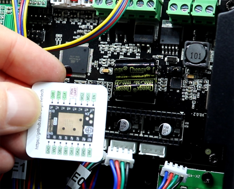
Now we unplug the printer again, then carefully pull the five old StepSticks out of their sockets and plug in the new ones, but don’t glue on the heat sinks yet, because we’ll do that at the very end. It is important to be very careful not to accidentally put the StepSticks in the wrong position and to pay attention to the direction. The StepStick pinout is shown on the small piece of paper.
3D Printer StepStick Set Voltage …
You can calculate the required voltage with Vref or RMS (Root Mean Square) and the maximum current per phase winding, but then you have to calculate down again a bit anyway, because you actually don’t set to the full rated current after all. For this reason, we have not opted for a formula, but for practical values and set the values like this:
<- Power supply E1: 0.95V, E0: 1.1V, Z: 0.95V, Y: 0.95V, X: 0.95V Display ->.
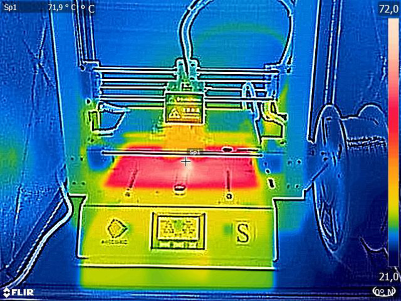
If one of the steppers skips individual steps or does not run cleanly, the voltage can be increased slightly. However, if one of the stepper motors heats up more after a longer runtime (depending on the stepper motor from approx. 45°C), the voltage should be lowered again a little. In retrospect, we would perhaps lower the extruder voltage (E0) a little, but in our case only the heating bed and the nozzle became warmer than 45°C 😉
The voltage is set by means of a potentiometer, which is used to decrease the voltage clockwise and increase the voltage counterclockwise. As a measuring point you can choose a free ground on the housing and as a second measuring point we choose the upper of the three measuring points for these StepSticks or alternatively attach an alligator clip to the small screwdriver with which you then set the voltage and directly receive the measurement.
We put a heat shrink tubing on the measuring contact so that we don’t accidentally connect another contact. Here you can see a small animation how to measure the voltage of the StepSticks.
Now unplug the power supply and carefully glue the small heat sinks onto the StepSticks and we are done with the stepper driver change.
3D printer firmware update …
As mentioned at the beginning, at this point we would now need to reverse the polarity of the pins inside the connectors to get the stepper motors to move in the correct direction with the new driver ICs. Since we were planning to change the firmware anyway, we now just downloaded and installed a current firmware with changed axes.
There are numerous options and which firmware you choose is certainly a matter of taste. Speaking of taste, we chose the Knutwurst 1.2.0 Marlin-2-0-x-Anycubic-i3-Mega-S with said TMC mod (MEGA_S_TMC_v1.2.0.hex), but of course the exact version depends on the 3D printer and mainboard used as well as integrated display, so be sure to identify mainboard and display type first, then check their website and download the appropriate firmware there!
After downloading the firmware, you can install it on the 3D printer with Cura or PrusaSlicer by connecting to the PC or Mac with a USB cable, then clicking on Settings -> Printer -> Manage Printer in Cura, then selecting the printer and clicking on Update Firmware.
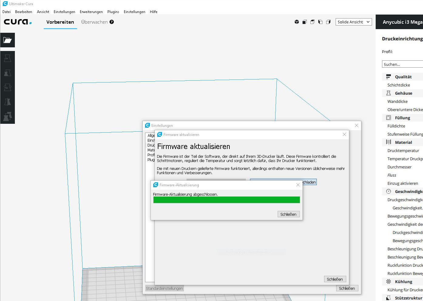
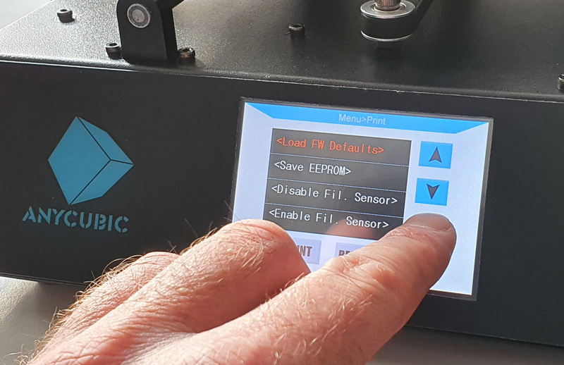
Important! As always, you must not interrupt the firmware update process, otherwise the mainboard could become unusable in the worst case, so do not interrupt! After the firmware update the 3D printer restarts automatically, where you should first load the firmware defaults via the new SD card menu, then select Save EEPROM (selected via the update button).
In the slicer software, you could now even increase the print bed size on the Mega S or Mega Pro, because the new firmware allows that as well.
Another important setting after the firmware update is the maximum speed of the component fan, which must be limited to 70% so that it runs at 100% speed at 12V.
In addition, you could now also calibrate the extruder, perform PID tuning and, above all, perform an extended, manual mesh leveling in the Special menu, which moves to several points (Next Mesh Point) after briefly heating the heating bed and saves these Z positions (Z+-0.1 or 0.02) with the new mesh leveling (only necessary for 3D printers without BLTouch autoleveling sensor).
Now the 3D printer is pleasantly quiet and we can make further improvements.
Perform 3D printer heating bed insulation …