
IR Extender Function and Infrared Repeater USB Edition Circuit Diagram
How the IR repeater works …
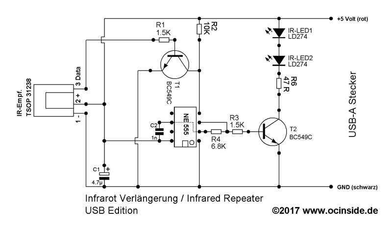
First, I would like to explain briefly here, how the IR-Repeater works.
When an infrared signal hits the TSOP31238, it is routed to the BC 549C NPN transistor, which transmits the signal to pin 4 (RST) of the NE-555 timer IC, wakes it up via reset and causes it to output an oscillating signal to pin 3 (Out). This signal is now output with the second BC 549C NPN (you can also use a more powerful BD 139) transistor to the transmitting diodes. A control LED is not necessary this time because no battery is used. Since the modulation of the NE555 oscillator depends on various factors, including the input voltage, a 7805 voltage regulator was used for 9V battery operation, which reduces the battery voltage to 5 volts. With the new USB circuitry, this is superfluous.
The TSOP31238 is relatively insensitive to interference and works with a large number of remote controls, but it can still happen that a device cannot be operated. If signals are continuously output to the IR LEDs (check with the smartphone camera), this could be triggered by high-frequency light from a fluorescent tube or LEDs, for example, or by the backlighting of LCD TVs. A light cover could already help here, giving the TSOP IR receiver some shade. Otherwise, just try a different position of the receiver part.
The circuit could also be constructed with fewer components and e.g. remove the tantalum capacitor and the transistor at the input of the NE-555 IC, but the NE555 would oscillate without the transistor, so that signals are transmitted continuously and would consume more power.
Here is the diagram that we designed for this IR repeater guide …
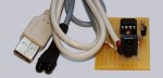
The components can be ordered as a kit in the Fanshop and can be combined e.g. with the USB Ultra IR v2.0 Kit.
USB IR-Repeater Soldering …