
The USB IR Repeater Soldering Instruction
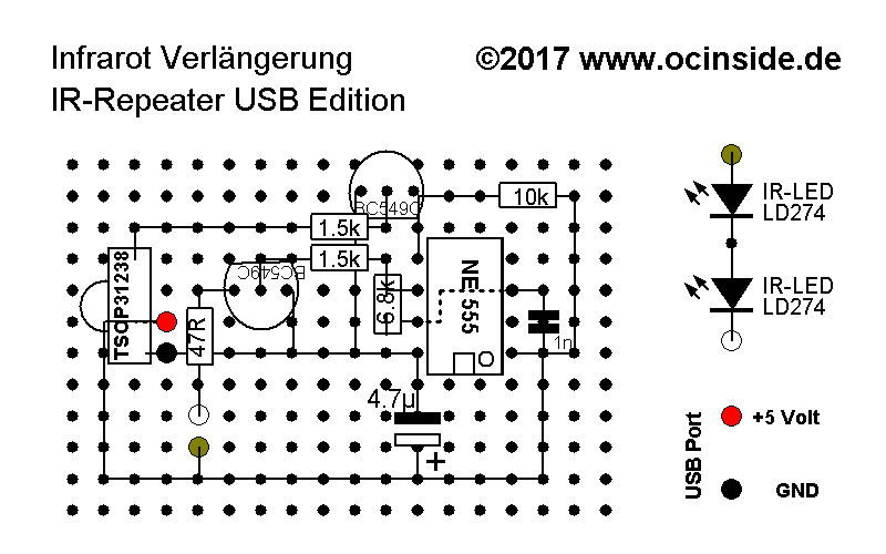
But now enough theory, let’s go to practice … Here is a representation of the PCB with all components and connections, which you can have a look at, while the 15 – 25 watt soldering iron heats up 🙂
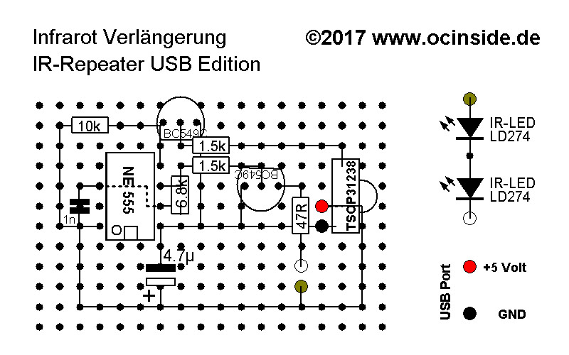
The correct attachment of the components …
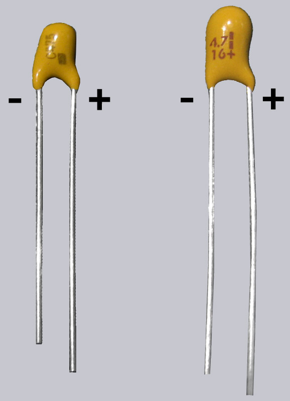
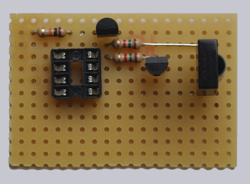
First, we start to plug the components onto the 18 x 12 holes of the breadboard as shown. For better hold, the pins underneath the PCB can be bent slightly. But please do NOT shorten the pins! It is important that the small notch of the IC socket and later also the IC point downwards. The small BC 549C transistor on the NE-555 has a flat side facing downwards, the other BC 549C has a flat side facing upwards. The polarity of the LEDs must also be correct. As you can see the polarity of the two light emitting diodes, you can see on the picture. Furthermore, it is essential to pay attention to the correct polarity of the small yellow 4.7 µF tantalum capacitor, where the positive pole must also point downwards! Next to the 16 is a small plus (+) sign on the component, which must point away from the socket. There is no polarity for the other components, so only the correct position is important.
Here is a picture of the different tantalum capacitor designs and polarity:
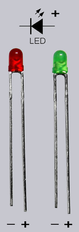
Optionally a control LED can be soldered in, so here is a picture of the LED’s polarity. The shorter leg with the larger connecting surface and the reflector inside the LED is the cathode / GND / ground / – / VSS. The longer leg with the smaller connecting surface inside the LED is the anode / + / VCC:
So the first step looks like a photo from above.
When all parts are attached as shown and fixed a little bit, the underside of the part is moved on. So that you don’t have to turn the board over and over again to locate the components, we have also created a mirror image of the board for better orientation.
Mirror-inverted display for better orientation on the underside …
The correct bending and pinching of the pins …
Now you should bend all pins of the components and now pinch them off, whereby you should make sure that all components are in the correct position and, as explained above, the polarity is correct. If you make a mistake at this point, it’s pretty hard to iron out later and all the work was for nothing. Take your time and rest to bend everything 100% and pinch it to the right length, which is no problem with a pair of pliers and a small side cutter.
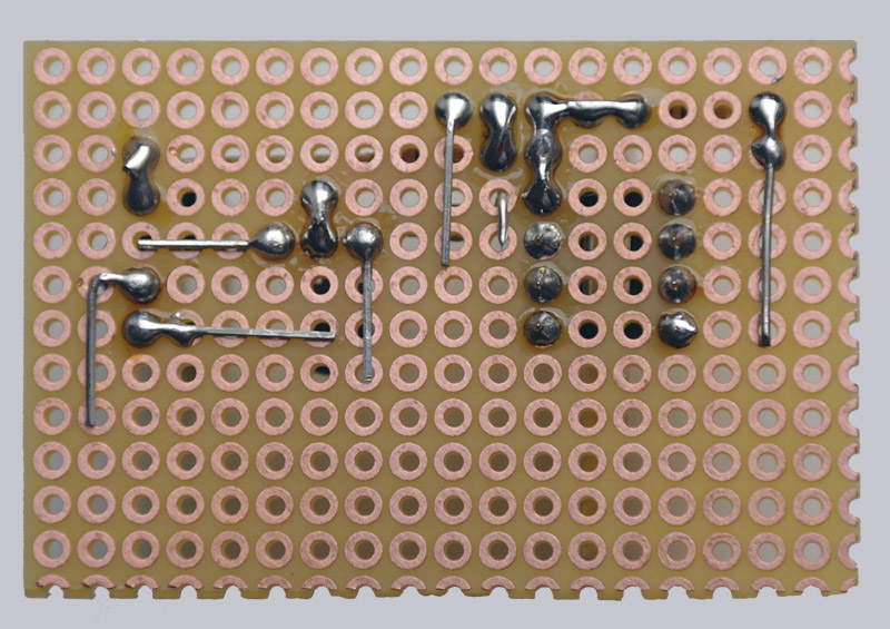
This is what the bottom looks like in the first step after bending and pinching the pins.
The next components are then plugged on as shown in the illustration. The 6.8K resistor close to the IC socket is inserted vertically into the PCB by bending a little leg 180° first and then inserting the resistor into the PCB. If you have ordered the larger IR-Repeater Box (or the smaller IR-Box without battery compartment) from the Fanshop, you want to use the TSOP on end. We left the TSOP’s legs a little longer to be able to fold it forward and mounted the USB IR repeater this time (as an IR repeater for the quite noisy Telekom Media Receiver 303, which was now placed on another floor) in a very flat housing. It’s up to you to decide.
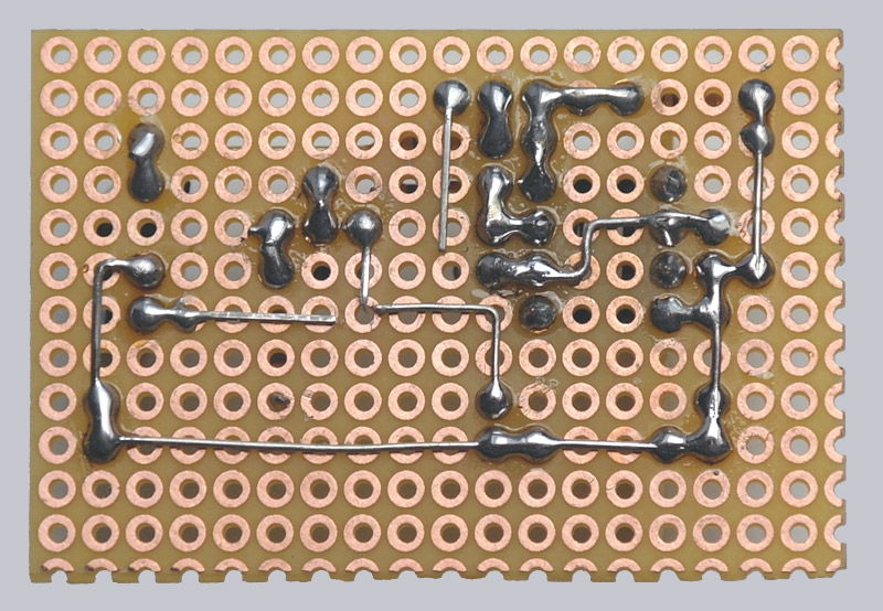
Solder only the pins of the components shown on the picture …
First we solder all pins on the underside of the board as shown in the following picture. Please do not solder more pins than shown in the illustration, because we will use the other cables soon. In this case, it is essential to observe all clearances where connections are not allowed!
This is what the bottom looks like in the second step after bending and pinching the pins.
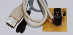
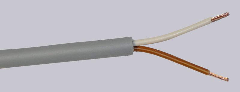
Prepare cable …
This is how the cables are prepared on both sides …
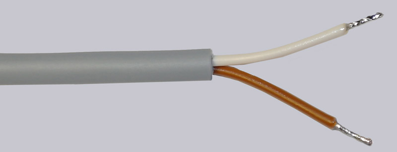
First strip the cables.
Then tin the open cable ends with a little solder.
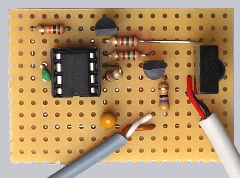
Insert the cable into the correct position of the board …
The white wire of the 2-core, approx. 150 cm long cable is plugged into the 47 Ohm resistor and the brown wire points to the lower long connection. Then plug the black cable of the USB cable into the bottom pin of the TSOP IR receiver and the red cable of the USB cable into the middle pin of the TSOP IR receiver. The other two cables (green and white) of the USB cable as well as the shielding should be clipped off and completely removed. If the shielding is not removed 100%, the shielding could possibly reach another component out of provided and this must be absolutely avoided – i.e. in case of doubt use a piece of shrink tubing or adhesive tape for the insulation. Furthermore, the two cables could be fixed to the PCB with small bridges from the remaining pieces of wire.
Solder the remaining connections …
Now solder the remaining soldering connections as shown in the illustration, paying attention to all gaps – e.g. DO NOT solder the two pins of the capacitor together!
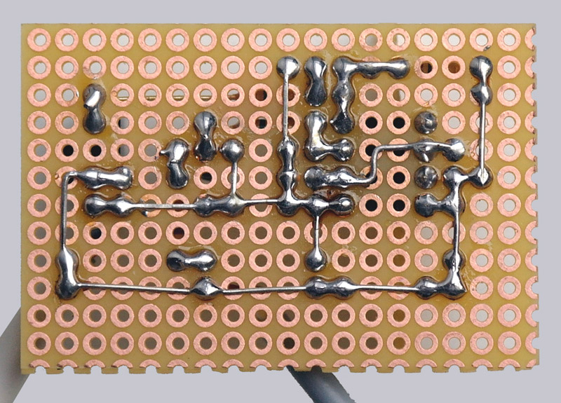
Finished circuit boards underside …
Here is a picture of the soldered PCB bottom side.
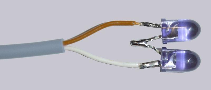
Solder infrared light emitting diodes …
The two IR transmit LEDs are simply soldered to each other with the long and short lead, so that the two LEDs are connected in series (positive pole to negative pole of the other LED). If you want, you can solder the two IR-LEDs to a separate cable and then connect the two cables in series as above with the two LEDs, but of course also pay attention to the polarity. The two infrared light emitting diodes are soldered together to the brown-white cable.
Insert the IC correctly …
Now insert the IC with the IC notch (or dot) to the IC socket notch (on the following picture to the left).
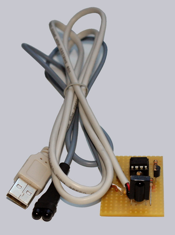
The USB infrared repeater is ready … 🙂
The best thing to do is to check all soldering points and the correct polarity of all components and cables. It’s already quite late to discover errors, but better late than never and you can’t control often enough. If there is really a mistake and it is not so easy to solve, I will stand aside with a few tips by mail or in our forums.
IR-Repeater USB operation …