
The first IR repeater Commissioning …
Now we finally reach the most beautiful point of the whole work …
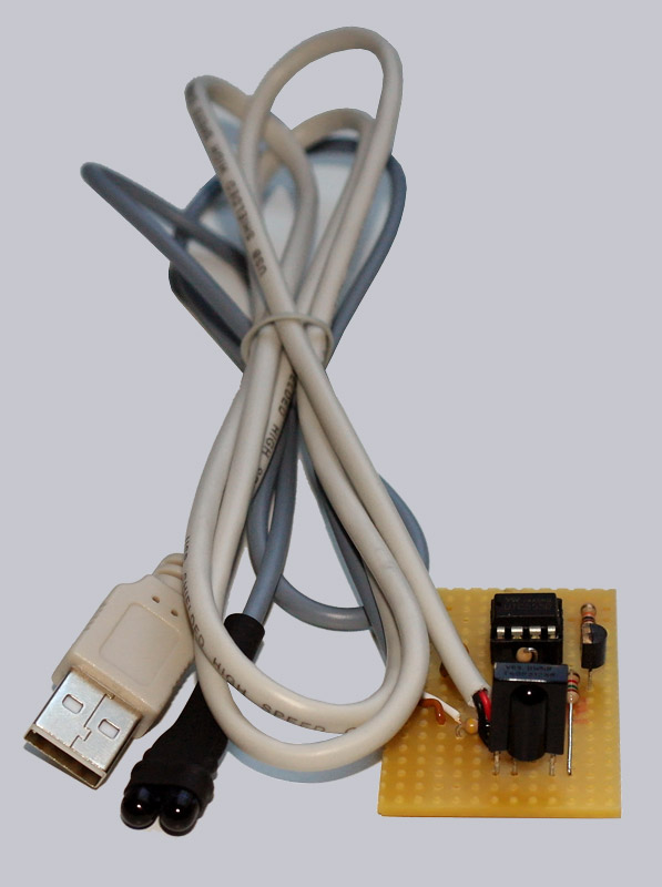
Connect the USB IR repeater …
If you have soldered everything and checked it several times, you can finally connect the IR repeater to carry out the first test run. We would like to recommend that the IR Repeater is not yet connected directly to the USB port of the PC or the TV USB port, but rather to an external USB power supply or an active USB hub with power supply. If you soldered anything wrong, something could be destroyed – protection functions at the USB port should prevent this, but you can’t exclude it 100%. We assume no liability whatsoever! Please also make sure that neither the underside of the PCB nor the vacant areas of the IR emitting diodes come into contact with metallic objects, i. e. do not place the PCB without insulation on a metal housing!
USB IR-Repeater / IR-Extender use …
Now simply take a remote control or an universal remote control, point in the direction of the TSOP 31238 infrared receiver and press any key, e.g. power. The two infrared light emitting diodes should now send signals and thus control the respective devices.
Infrared Tips and USB IR-Repeater FAQ …
Here are a few tips on infrared signals and a FAQ or help for the IR-Repeater USB Edition.
– Infrared signals cannot be seen with the eye, but if you look at the infrared signals through a digital camera or with a smartphone camera, the infrared light becomes visible. This way, you can quickly see whether the remote control’s battery is empty and whether the IR repeater is transmitting signals.
– If the IR extension emits continuous signals, high-frequency light may interfere with proper infrared reception, which could be emitted by neon lights, fluorescent tubes, LEDs, or the backlighting of LCD TVs with CCFL backlighting. The IR-Repeater reproduces the infrared signals. In this case, place the receiver of the IR repeater in the light shadow and not too close to the LCD TV. Such sources of interference should also be avoided without an IR repeater on every IR receiver.
– If a remote control does not work properly with the IR repeater, you may be able to vary the R4 resistance value slightly to change the NE555 modulation frequency. It can also be used for unusual infrared codes by soldering a 1K resistor in series to a 10K potentiometer instead of R4. But first you should check if everything is soldered correctly and other remote controls work. Furthermore, you should clarify which coding and modulation frequency is used by the remote control. The TSOP31238 is designed for 38 kHz and works e.g. excellently with RC5 and RC6 encoded signals.
– The IR repeater should be placed in a small enclosure (IR Repeater Box is available in the fanshop) and the transmitting light emitting diodes should be carefully insulated, e.g. with shrink tubing or some adhesive tape.
– To stabilize the cables, it is possible to tie them together with a cable tie inside a housing and then lead them out of the housing. This provides excellent strain relief.
– If there is only little soldering experience, you should first practice on an old board so that the solder joints will be good at first sight. If you don’t get along with soldering, you can easily post a message in our forum under Electronics, because we have a lot of helpful readers in our forum, who will certainly help us.
– If you need a slightly larger circuit board, a slightly longer cable or a small piece of heat shrink tubing to insulate the transmitting LEDs, you can enter this in the fanshop message box when ordering. Perhaps the wish can be fulfilled 😉
In the OCinside Fan Shop you will not only find our fan articles, but also all components for the IR-Repeater as inexpensive kits. We look forward to your support. The editors of ocinside.de say thank you for buying!
Continue to the fanshop with the OCinside.de electronic kits and fan articles …
Discuss about the USB IR repeater in the forum and share experiences …