
It is time to solder again on OCinside.de today. With an IR repeater you can place your HiFi equipment and the TV receiver in a cabinet or even control the PC or HTPC with IR receiver via the infrared remote control in another room. This new IR-Repeater is designed as an USB Edition, so that you don’t need a battery as power source, but can use it directly on an USB port. All components for soldering the new IR-extender are available as an inexpensive kit in the OCinside.de Fanshop. So heat up the soldering iron and enjoy reading and soldering.
The purpose of the IR repeater …
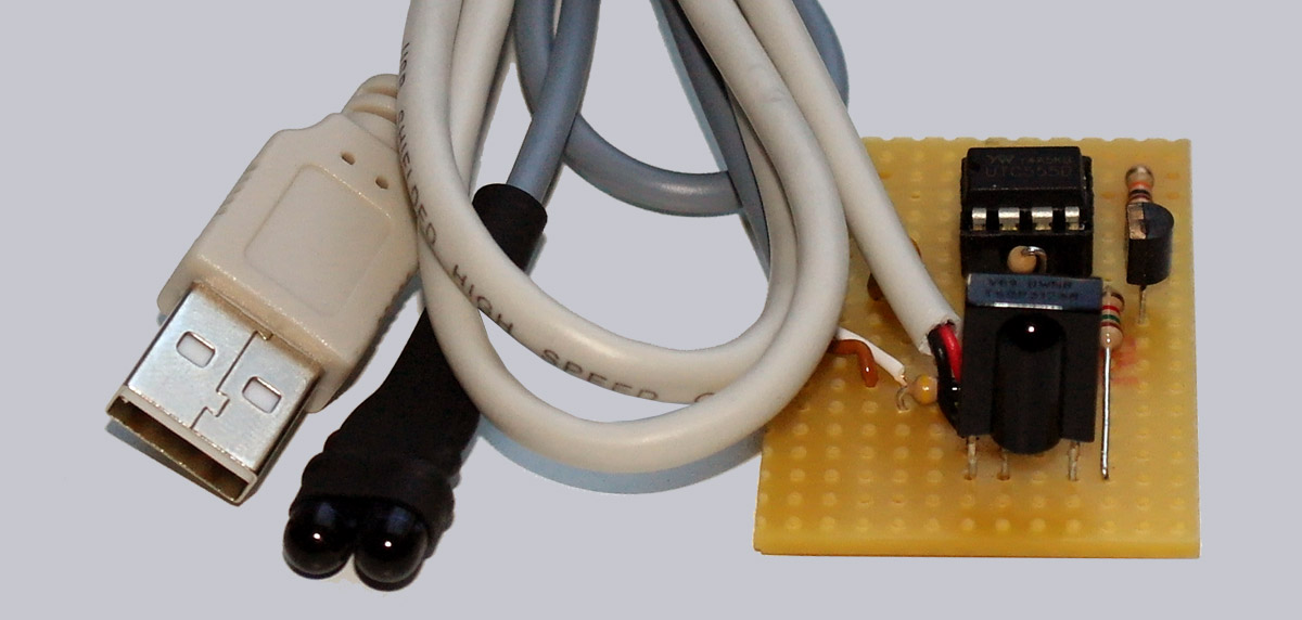
If you want to hide your HiFi equipment, DVB receiver or HTPC with USB Ultra IR-receiver, e.g. in a cabinet or even behind a wall, you know the problem: How do you get the infrared signal from the remote control to the respective device? For this purpose the IR-Extender or IR-Repeater schematic with the self-assembly instructions has been developed. The infrared signals from the remote control do not pass through a wall or into the rack, so this IR extender receives the IR signals, modulates the signals and routes them via a 2-pole cable to two IR transmitters, which send the signal to the respective HiFi device, HTPC, media player or PC with IR receiver. For example, you can mount a television in the living room and place the receiver in a cupboard or operate the equipment from a completely different room using a conventional remote control. Remote control DVB Receiver or HTPC in the basement becomes child’s play. The 2-pin cable can be several meters long and can even be used without shielding, e.g. you could stow a thin cable in the floor strip or drill a small hole through the corresponding wall and then put the cable through. Even a distribution of the IR signals over several floors would be conceivable, because even 100 meters of cable to the transmit diodes should not be a problem. Depending on the remote control, device and IR coding, the IR emitting diodes can be placed approx. 20-30 cm away from the IR receivers or mounted so that several devices can be controlled simultaneously via additional IR emitting diodes. Whether you solder the two transmit diodes directly next to each other or give each IR transmitter its own cable for different transmit positions is up to you.
These parts are required …
The components are available as kit in the fan shop.
Here’s a short YouTube video in German with English subtitles.
Note: Please allow our cookies first to see this external content!
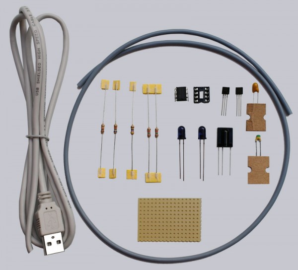
1x Vishay TSOP31238 (38 kHz infrared receiver)
2x LD274 infrared emitting diode
1x 8-pin IC socket
1x NE 555 IC
2x BC 549C transistor
1x 4.7µF 16V capacitor (electrolytic capacitor or tantalum) upright version
1x 1nF capacitor (ceramic layer or multilayer) standing version
1x 47 Ohm resistor (0.25 W)
2x 1.5 K resistor (0.25 W)
1x 6.8 K resistor (0.25 W)
1x 10K resistor (0.25 W)
1x breadboard Euro board (an approximately 4.7 x 3.3 cm small piece of 18 x 12 holes are enough)
1x at least 2-pole 1.5 meter cable
1x approx. 1 meter cable with USB type-A plug
Circuit diagram of the USB IR repeater …