

The Retro Gaming Handheld Display …
We start the construction by modifying the display for use in our Retro Gaming handheld. For the picture display we use a 3.5″ TFT display in 4:3 format, which is actually intended for use in the car to display the picture of a rear view camera 💡
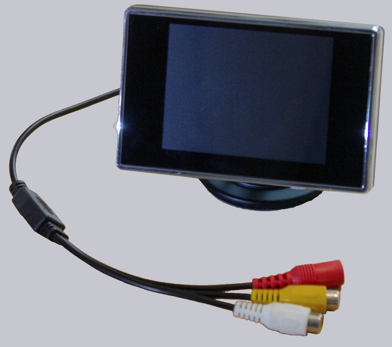
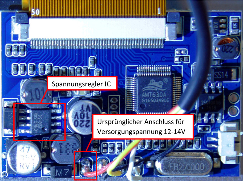
Therefore we remove the actual display including the control electronics from the case and the electronics is converted from the originally intended car operating voltage 12-14V to the operating voltage of our Retro Gaming handheld of 4.5-6V. Fortunately, this modification is relatively simple, as the electronics of the display are designed exactly for the battery voltage of our Retro Gaming handheld and an extra voltage regulator IC is connected upstream to convert the 12-14V of a car to 5V, which we will now upgrade. The voltage regulator IC in our case is called 1509-5.0, whereas the “5.0” stands for 5V.
Here you can see a picture of the complete control electronics of the display with the voltage regulator IC 1509-5.0.
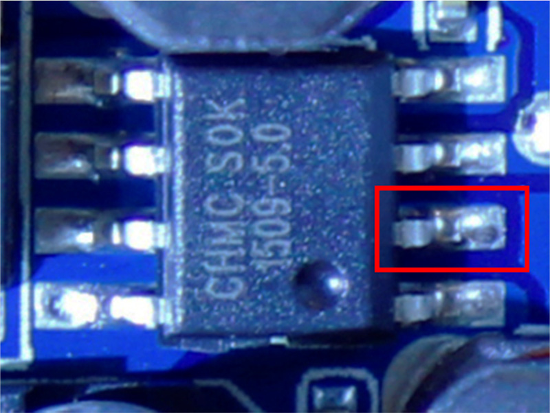
And here an enlarged representation of the chip with the designation 1509-5.0 – according to the data sheet there is an output voltage of 4.8-5.2V on the red marked pin 2.
We remove the chip and solder the switched positive pole of our battery instead to the contact point where pin 2 of the voltage regulator IC was soldered before. In addition, the two possible video inputs are marked, but we only need one of them. The second input remains free.
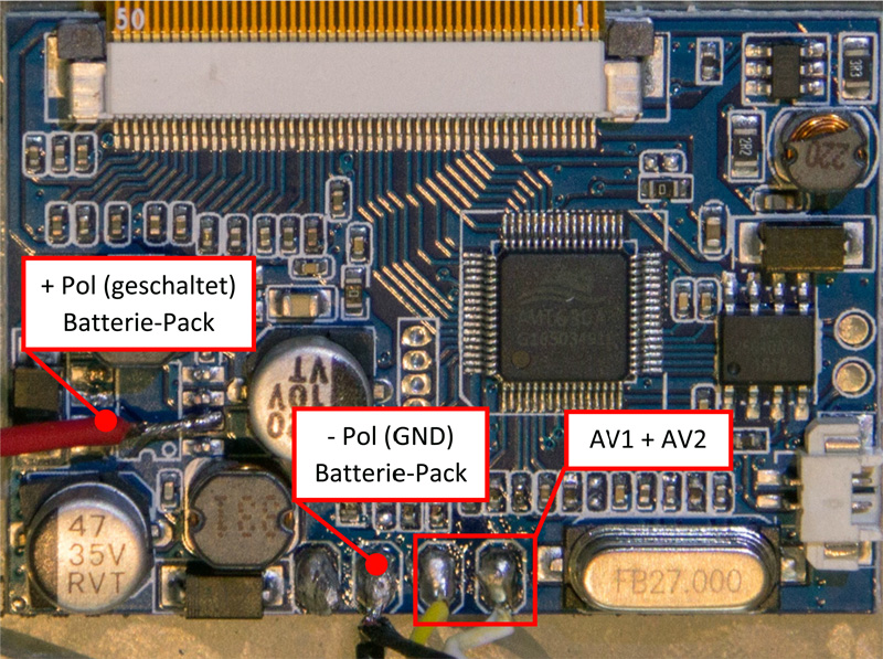
The video inputs are Composite/FBAS compatible, which means we won’t be able to enjoy HD quality later. But that’s not too bad, because the games we can play later on our handheld come from a time when there was no HD TV and the games are therefore optimized for the lower resolution of the display.
Only the menu display of the used Recalbox user interface will be a bit difficult to read in the default setting, which we will fix with a modified configuration file and will describe later in our How-To. Also, the aspect ratio of 4:3 fits better to the old games than a modern 16:9 display. Further adjustments to the display are not necessary.
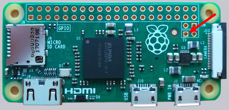
In the following picture you can still see the connector for the video output of the Raspberry Pi Zero. The rectangular solder socket in the “TV” field, surrounded by copper, is connected to one of the two video inputs on the display.
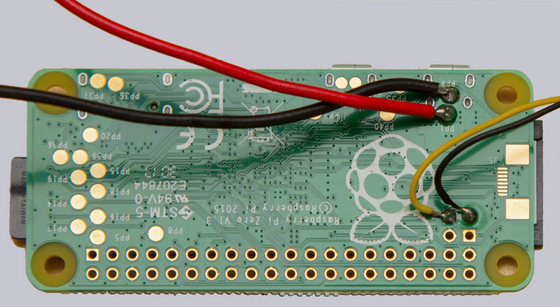
However, the cable for video signal transmission is soldered from the underside, which makes later assembly easier. Here you can see the video signal line soldered from below. The thin black ground wire is not actually necessary for the video signal transmission (since all ground wires are connected via the battery minus pole) but does not harm either.
Continue with the Retro Gaming handheld front and buttons …