
Retro Gaming Handheld mit Raspberry Pi Zero assembly …
All important precautions are now taken and we can assemble our Retro Gaming Handheld ready.
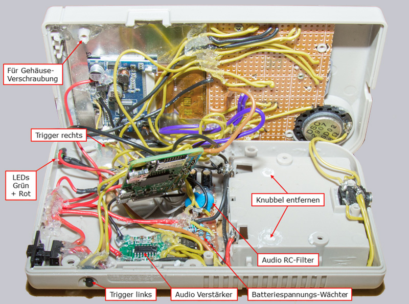
Now it’s time to bring all components inside the case into their final position without damaging any of the sensitive cables or their solder joints. Most of the elements are fixed in place with hot glue, and most of the solder joints of the cables are covered with hot glue to protect the cables from breaking directly at the solder joint, because during assembly you have to move and press the cables a little bit here and there to make sure everything fits.
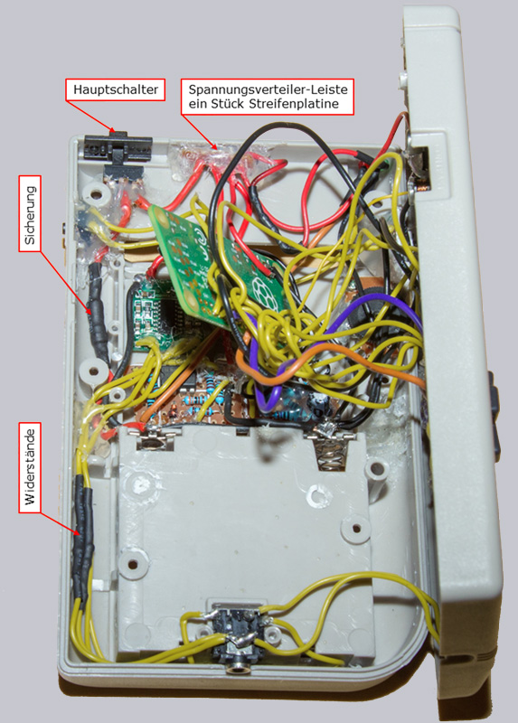
For the LEDs you drill 2 holes with a 3mm drill bit in the upper right corner of the lower half of the housing. In order to be able to summarize the whole supply lines for all components simply, we cut a strip from a strip board and soldered all cables to it.
As left and right trigger buttons we soldered micro buttons out of an old DVD player. This type of push button is used in almost every electronic device with push buttons. The left button can easily be inserted through the original opening for the power cord plug and fixed there with hot glue. We soldered the right trigger button onto a tiny piece of hole grid board and placed it in the opening where the link cable of the original Game Boy was plugged in.
Here you can see the resistors, the fuse, the main switch and the voltage distributor board.
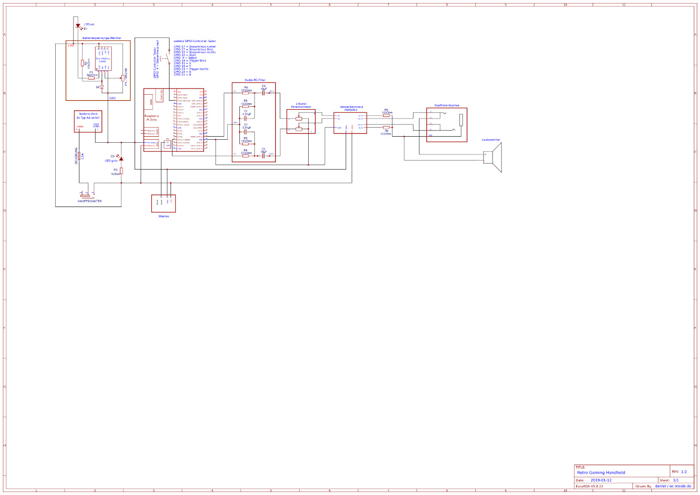
The complete circuit diagram can be viewed or downloaded here.
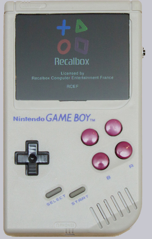
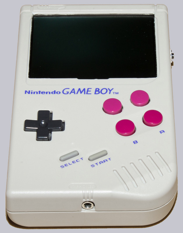
And completely assembled, the Retro Gaming handheld looks like this.
Here you can see again the main switch and the two LEDs.
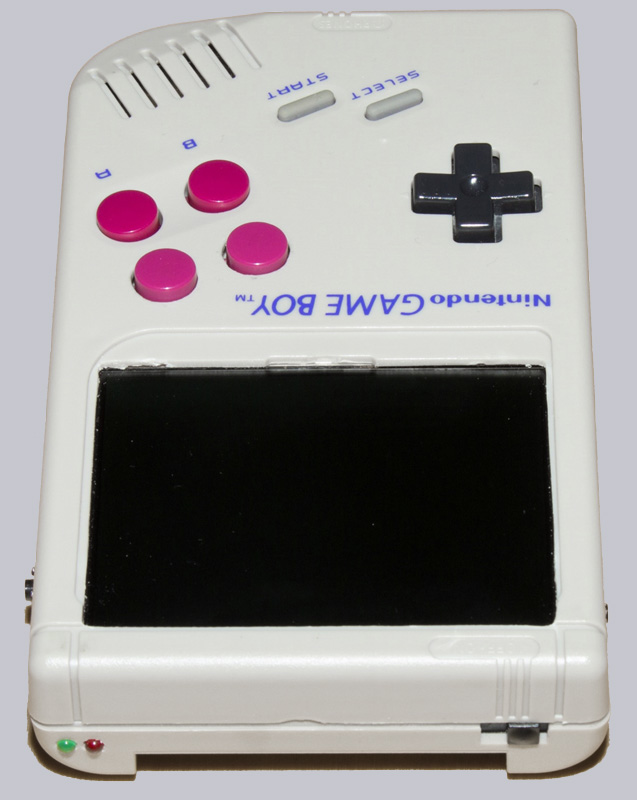
Here you can see the volume control and the right trigger button.
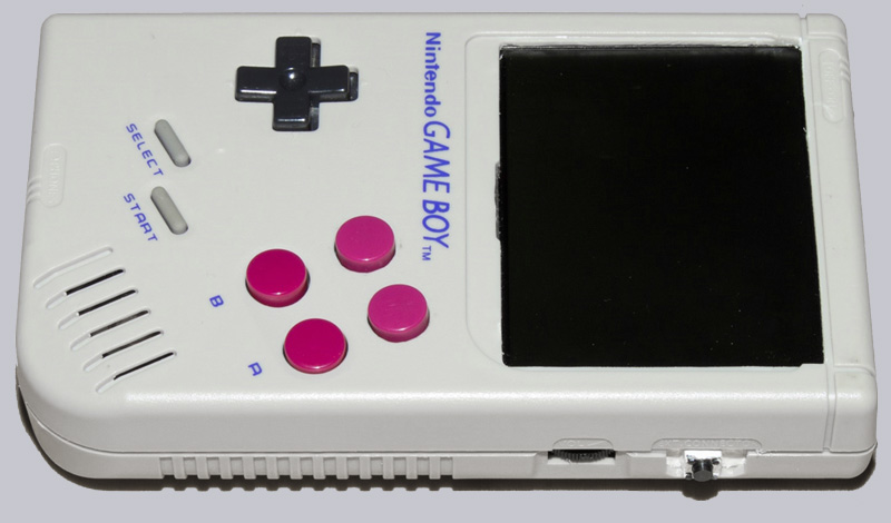
The following picture shows the left trigger button.
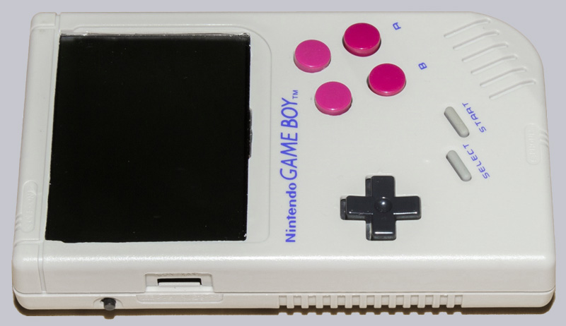
The jack socket was fitted at the bottom.
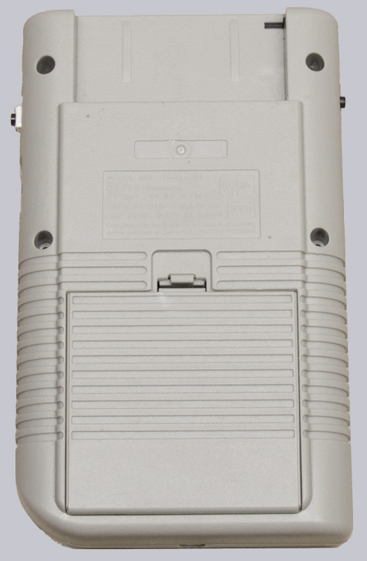
And on the back is the battery compartment for conventional Mignon batteries or rechargeable batteries.
Retro Gaming Handheld Result and general impression …