

Raspberry Pi Zero Retro Gaming Handheld speaker …
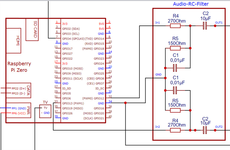
Now we come to the audio section of our Retro-Raspboy. According to our programming the Raspberry PI will output via GPIO 12 and GPIO 13 stereo sound as PWM signal. Since the Raspberry Pi Zero, unlike the Pi 2 or Pi 3, has no integrated audio filter on the PCB, we have to build a simple RC filter ourselves before we pass the signal through the potentiometer for volume control and then use the amplifier module to increase the power to loudspeakers, which is sufficient even for powerful and power-hungry 32 Ohm on-ear headphones.
First, the RC filter is soldered as compactly as possible to a hole grid board using the following circuit diagram.
The components of the RC filter are as follows:
R4 = Resistor 270 Ohm
C2 = Electrolytic capacitor 10µF
R5 = Resistance 150 Ohm
C1 = Ceramic capacitor 0.01µF
Here you can see the circuit diagram for the RC filter and the connection to the Raspberry Pi Zero.
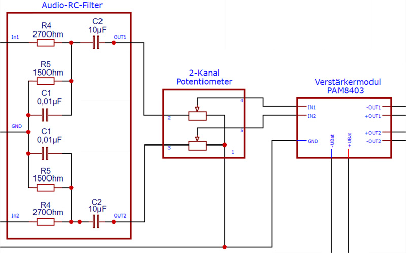
Then from the RC filter through the 2-channel potentiometer and into the amplifier module. The 2-channel potentiometer has 5 connections (1x ground, 2x input, 2x output via slider). From the slider outputs of the potentiometer the lines go into the amplifier module, which has the PAM 8403 IC built in as output stage, which with its 2x3W delivers far more than enough power for the internal speaker of our Retro Gaming handheld or also for powerful headphones. Since the PAM is designed for a maximum operating voltage of 6V, we have no problems with our operating voltage. You can get the finished amplifier module very cheap e.g. here at Amazon *Ad).
Here is the circuit diagram from the RC filter to the amplifier.
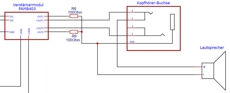
From the amplifier we then go to the headphone socket or the loudspeaker of our Retro Gaming handheld. Since we have to merge the two negative outputs of the amplifier at the headphone socket, we solder a 100 Ohm resistor into the wires. In this way we avoid short circuits, which would result in the amplifier being switched off for a short time.
Other Retro Gaming handheld instructions available on the Internet use an extra switch to switch between the internal speaker or the headphone output. This switch makes the headphone socket automatically, if you follow the pin assignment in our “How-To” exactly. The following picture shows the circuit diagram from the amplifier to the loudspeaker and the headphone socket (also called Audio Jack).
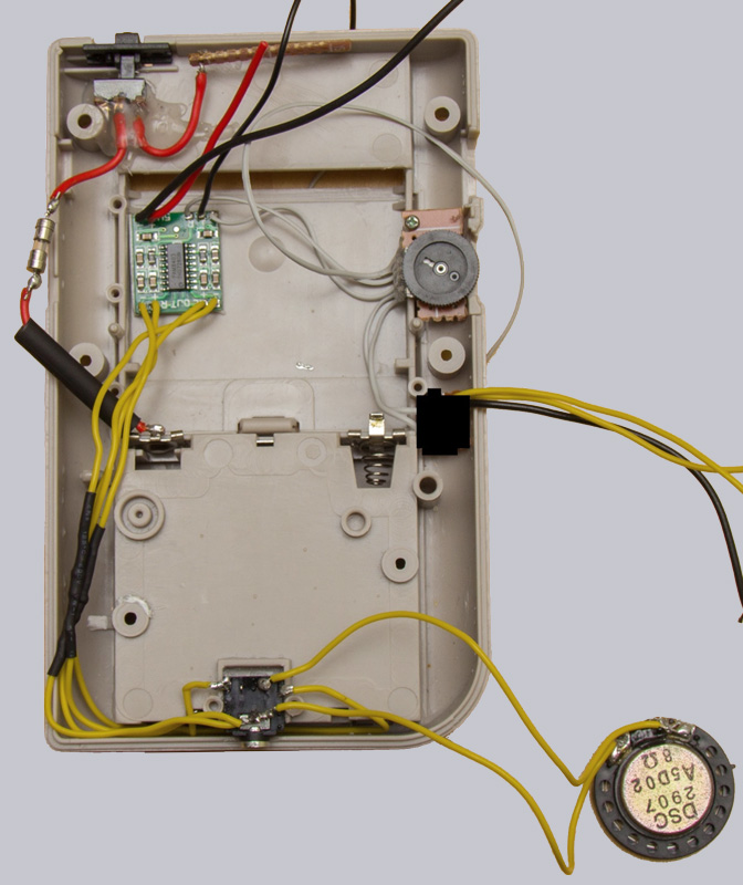
The next picture shows the wiring of the amplifier module. How the potentiometer for volume control is attached to the original place in the case can also be seen.
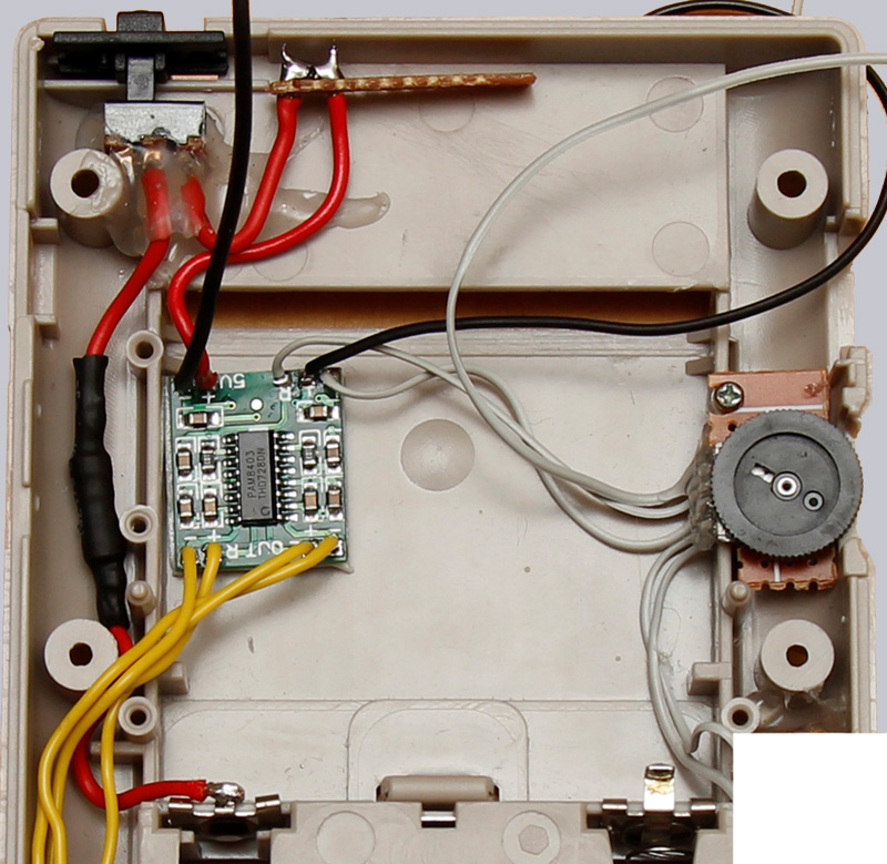
And here is a picture where you can see the loudspeaker and the fuse, which has not yet disappeared into the heat shrink tubing and is located between the battery and the main switch. The 2 pcs. 100 Ohm resistors between amplifier and headphone socket are already built in. Since the RC filter module was unfortunately not yet correctly built at this time, it had to be blackened on the picture unfortunately.
Continue with the Retro Gaming Handheld Emulator Software …