
Retro Gaming Handheld Button …
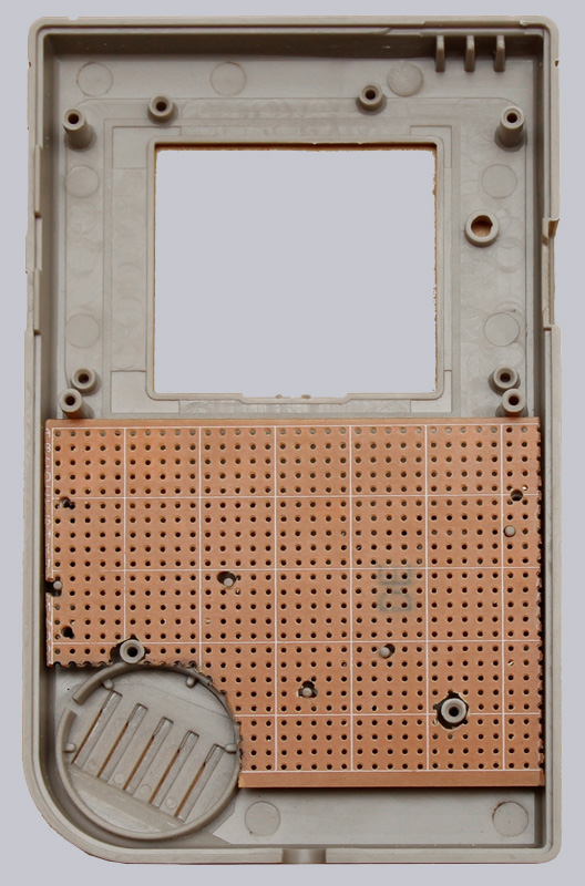
We stay on the front of the handheld and now focus on the case and the controller push buttons, for which we cut a strip board. In the lower part the board is still too long, later the board had to be cut off from below at the 3rd row to create enough space for the headphone jack. Tip: To separate the hole grid boards, simply scratch the top with a knife and then break off at a sharp table edge. Then the cutting edges will be even cleaner 💡
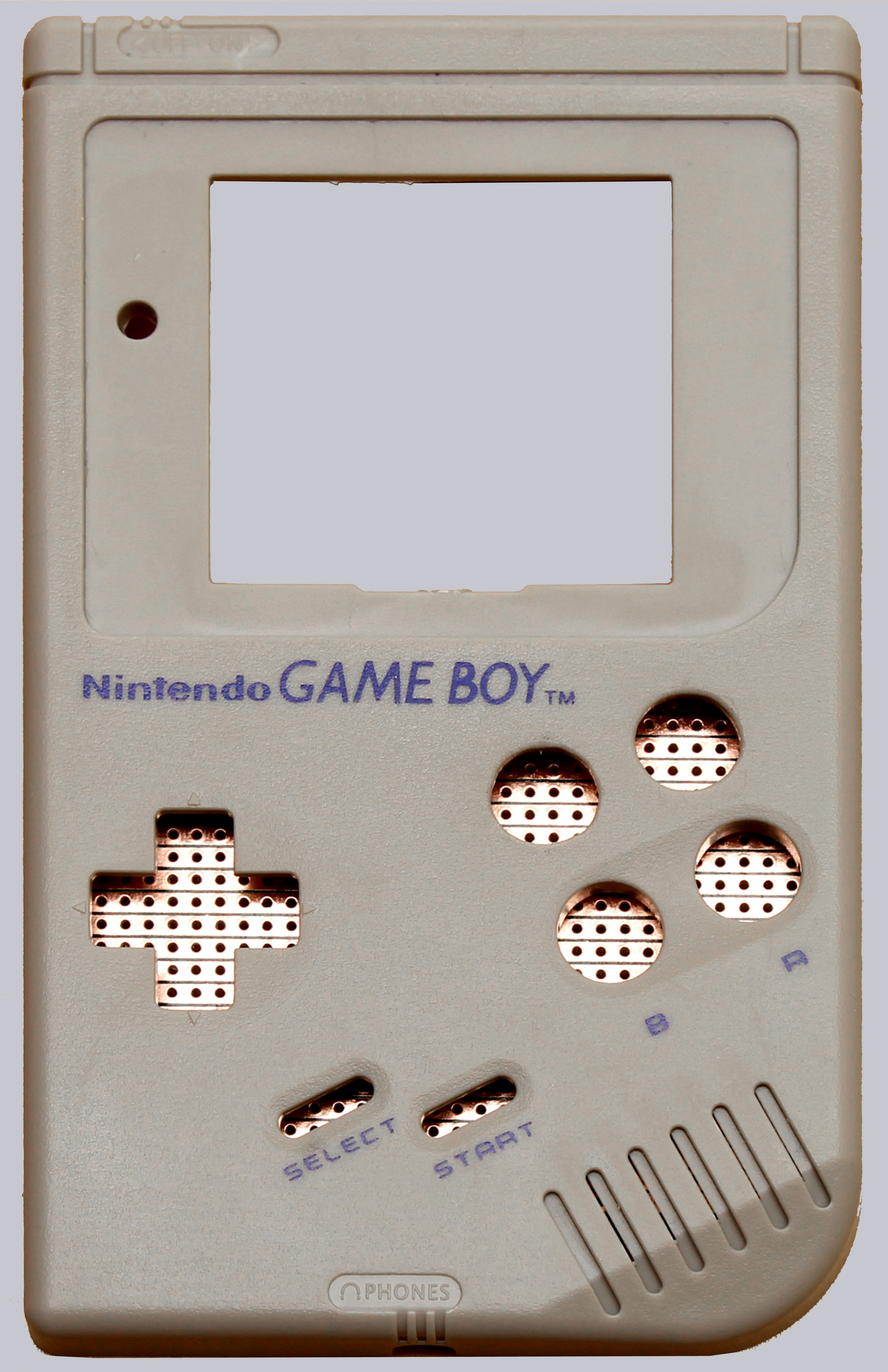
Viewed from the front, the individual copper strips of the circuit board are clearly visible. The additionally drilled holes for the X- and Y-button are already visible here. The distance to the A- and B-buttons is best defined by the rubber element of the push buttons, so that you don’t have to cut the rubber later (as you can see in one or the other tutorial of other websites).
A push button must always connect 2 strips to make electrical passage to the appropriate GPIO (input) on the Raspberry. When a push button is pressed, a ground connection must always be made to the respective GPIO, which means that one of the two strips connecting a push button is always connected to ground and the second strip leads to the GPIO on the Raspberry.
If a copper track on the board leads over several push-buttons (e.g. between the right and left button of the control pad), it must be cut through between the buttons with e.g. a knife (scratching away copper is enough), otherwise the Raspberry would switch several GPIOs at the same time.
The following picture shows the electrically conductive black rubber elements used to connect the copper tracks of our controller board.
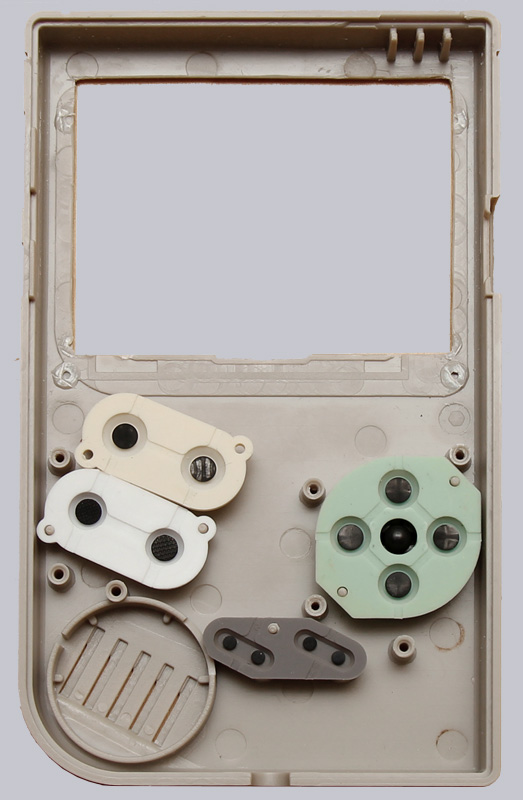
The cutout for the display was already enlarged and the 4 sleeves, where the case was screwed in the original condition, were cut off as close as possible to the bottom. These 4 plastic sleeves should be kept, as we will use them again later to screw the case together.
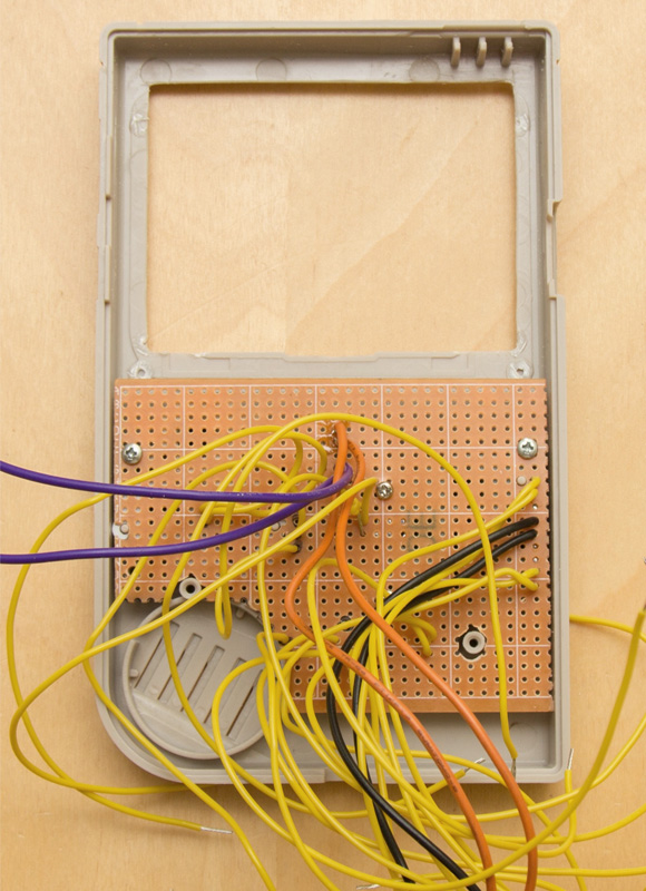
In the next pictures you can already see the mounted PCB with some cables, which will be soldered to the GPIO contacts of the Raspberry later on, as well as the ready built in controller push buttons X + Y (above A + B).
At this point we would like to recommend to use as thin as possible (max. 0.14mm²) and short cables for the controller contacts in order to be able to accommodate the cables more easily in the case later, otherwise there will be space problems when closing the case.
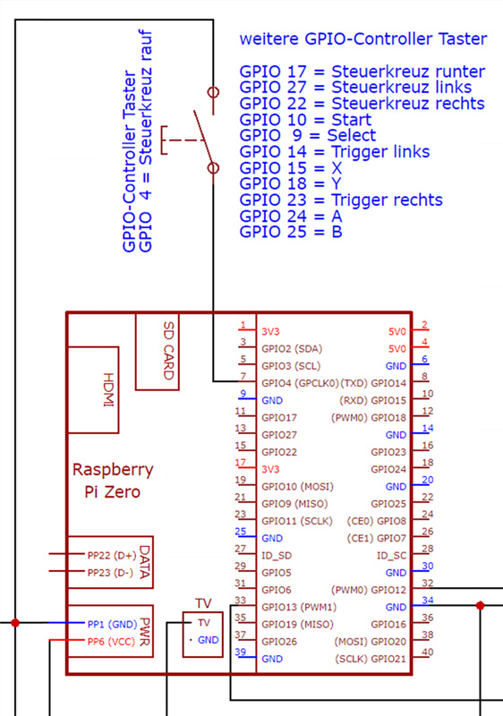
The assignment of the controller buttons to the inputs (called GPIOs) on the Raspberry Pi Zero is shown in the following schematic.
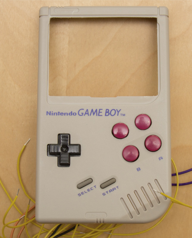
The housing now looks like this without a display.
The display and the speaker are positioned and fixed with hot glue. Hopefully there is enough hot glue available 😉
After that the front side is as good as finished. In order to be able to screw the case back on properly later, 2 of the 4 plastic sleeves cut out of the case were shortened by the thickness of the display and glued back to the original position on the display with hot glue. We won’t use the two middle sleeves anymore. 4 screws are sufficient to hold the case together properly.
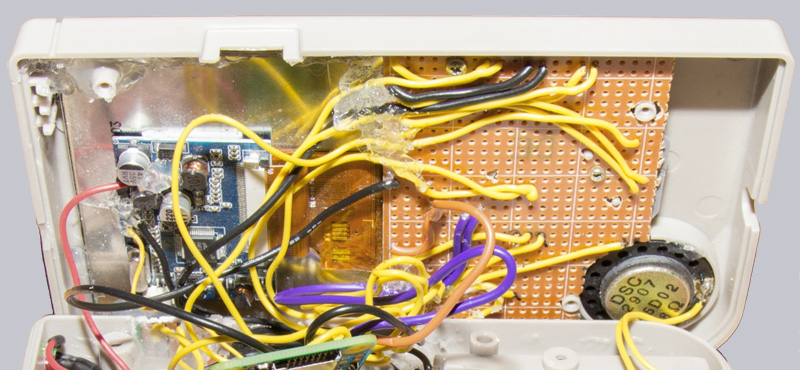
The following picture shows the finished front side with the shortened controller board from the inside.
Retro Gaming Handheld power supply …