

Retro Gaming Handheld battery operation …
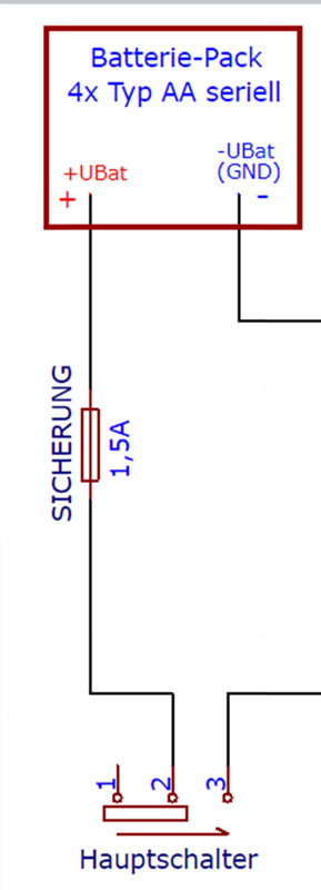
Let’s take care of the power supply now. Our Retro Gaming handheld is powered by 4 series-connected AA cells, which is 100% identical to the original Gameboy. Both dry cells with 1.5V or batteries with 1.2V cell voltage can be used, since the voltage regulator chip “PAM 2306” integrated in the Raspberry can be operated with up to 6.5V.
To be on the safe side, we install a 1.5A glass fuse between the battery pack and the main switch, so that nothing can happen later, even in the event of a (hopefully never occurring) short circuit. All components are supplied with power after the main switch, so that the entire system is completely disconnected from the power supply by the main switch and no creeping discharge of the battery cells by the connected components can occur when switched off.
Here you can see the circuit diagram for the power supply.
In addition, we install LEDs that indicate the operating status of the Retro-Raspboy and the voltage status of the battery. The green LED lights up when the main switch on the device is switched on and the red LED lights up when the battery voltage is low and the batteries should be recharged.
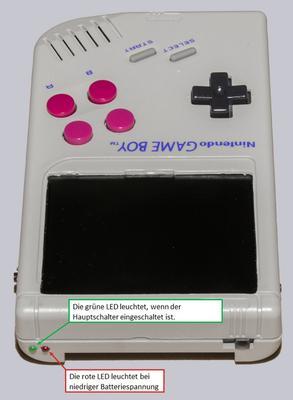
These functions were deliberately chosen. In contrast to many other projects that circulate on the Internet, where “stupid” electronic voltage monitors are installed, which interrupt the power supply without warning if the voltage falls below a preset value.
Downloading the Raspberry properly can damage the data on the SD card and cause the system not to start and to have to be completely reinstalled.
Therefore we deliberately choose “only” a display that reminds us to shut down the Retro-Raspboy in time and recharge the batteries. But there is no hurry, because we control the LED in such a way that the batteries are not discharged dangerously deep.
The following picture shows the circuit diagram for controlling the red LED.
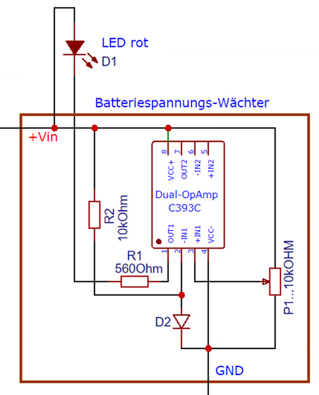
The following components were installed:
D1 = LED red Ø3mm
R1 = series resistor 560 Ohm for the red LED
D2 = silicon diode for the reference voltage (almost any diode, you can simply desolder a diode from an old device)
R2 = Resistance 10 kOhm
P1 = Potentiometer 10 kOhm for setting the voltage from when the LED lights up.
After setting the potentiometer, you can measure the resistance values and install resistors instead. We also did this on our circuit board, because this eliminates the risk of the potentiometer moving during installation and the resistors are smaller (lower height) than a trim potentiometer.
It makes sense to adjust the trim potentiometer so that the red LED starts to light up at approx. 4.7V, then there is still enough time to save your game and drive down the Retro-Raspboy without endangering the batteries due to deep discharge. In our case this corresponded to a voltage divider consisting of an 8.5kOhm resistor and a 1.5kOhm resistor. Since each electronic circuit is subject to certain manufacturing tolerances, the resistance values can always deviate a little.
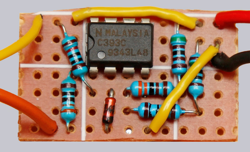
IC = C393C
However, any other IC with integrated operational amplifiers can be used (which is just what you have at hand).
The C393C has 2 integrated OP-AMPs, but we only use one of them.
Here is the original circuit diagram of the IC (source: NEC C393C data sheet).
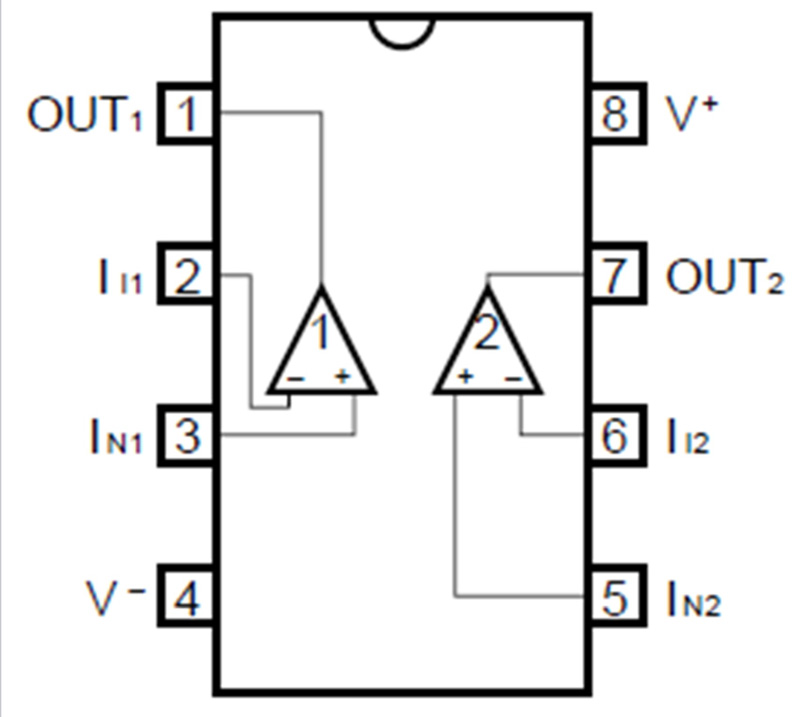
Pins 1, 2 and 3 are required for the circuit. In order for the IC to work, the IC itself must be supplied with power. Pin 8 must be connected to the switched positive pole of our battery and pin 4 to the negative pole of the battery. The permissible operating voltage of the C393C is 2-36V, whereby the operating voltage of the Retro Gaming handheld is between 4.5 and 5.6V depending on the state of charge of the batteries, or 6V if primary cells are used.
In the finished state our control board looks like this. Here the trim pot has already been replaced by resistors.
During the construction phase, of course, various tests and several restarts of the Retro Gaming handheld were carried out. Unfortunately it happened once that the main switch was not turned off after shutting down the operating system. This condition was not noticed until the next day, so that the power supply, consisting of 4 pcs. Ni-Mh rechargeable cells, in total only 0.4V!
Panasonic specifies a minimum voltage of 0.9V per cell in the Eneloop battery data sheet. If the voltage falls below this value, the battery will inevitably be damaged.
Although in our case the batteries could be recharged, they had practically no usable capacity and were definitely defective. For this reason we build an additional green LED in our handheld, which shows us that our gaming handheld is switched on, even if the Raspberry has already been shut down and the screen is completely dark.
The schematic looks like this.
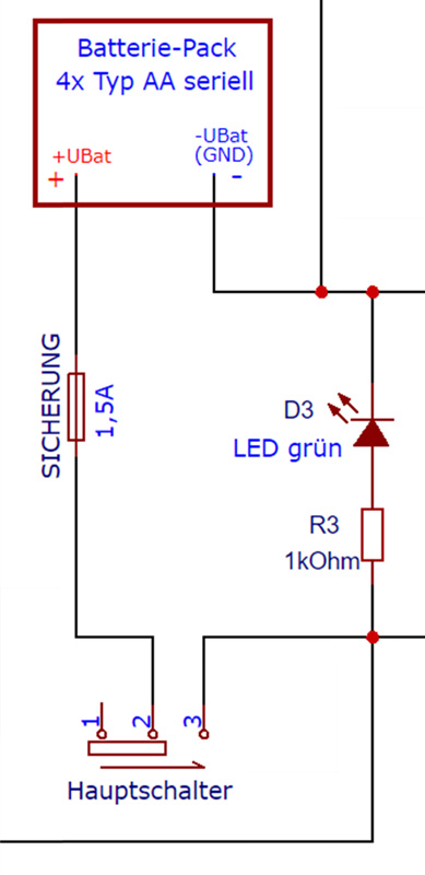
R3 = resistor 560 Ohm to 1 kOhm for green LED
With 1kOhm the green LED shines a little less penetratingly bright.
D3 = LED green Ø3mm
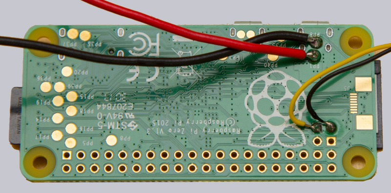
To power the heart of our Retro Gaming handheld, the Raspberry Pi Zero, wires from the main switch and negative pole of the battery pack are connected to the solder joints marked PP1 (+) and PP6 (-).
These solder joints are located on the underside of the Raspberry, as you can see on the following picture. The picture also shows that the video signal line has also been soldered to the underside. All wires are soldered from below, because we will install the Raspberry Pi Zero with the bottom side up into the back of the case, so that all wires are led away from the Raspberry.
This concludes the topic of energy supply.
Continue with the Retro Gaming Handheld Sound Output …