
Quickly to the right hardware equipment …
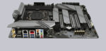
ASRock X299 Creator Layout, Design and Features
ASRock X299 Creator RGB lighting
ASRock X299 Creator Voltage Regulator and Heat Sink
ASRock X299 Creator Equipment
ASRock X299 Creator Expansion cards
ASRock X299 Creator Memory
ASRock X299 Creator Hard disk drive connectors
ASRock X299 Creator USB and Firewire
ASRock X299 Creator Network
ASRock X299 Creator Sound
ASRock X299 Creator ATX back panel connectors
ASRock X299 Creator PC System
Layout, Design and Features …
The black/light gray ASRock X299 Creator High Density Fiber Optic Sapphire Black PCB board makes a perfectly processed impression and dominates in the lower area with three heat sinks above the M.2 slots and one heat sink above the chipset. The motherboard features premium 60A power chokes, Nichicon 12K black caps capacitors, 13 power phase design and 7.1 HD audio via the ALC1220.
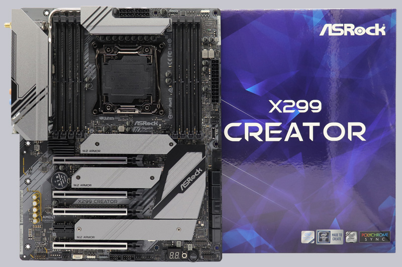
The ASRock X299 Creator has a Dr. Debug 7-segment LED postcode display, LED illuminated buttons for power, offers three fast Ultra M.2 slots for PCIe Gen3 x4 modules with up to 32 Gb/s connection. On the following picture you can see the five PCIe 3.0 slots and the three M.2 slots, all three M.2 sockets are equipped with heat sinks.
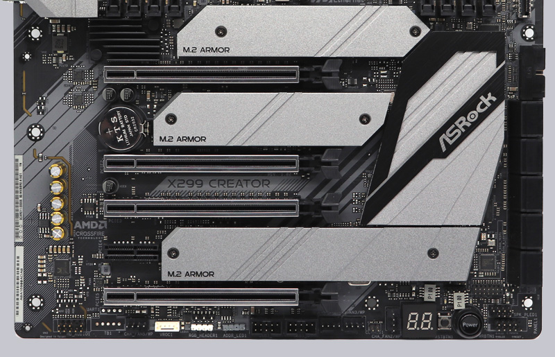
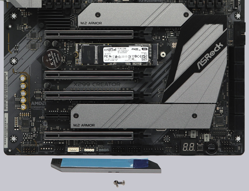
We have tested the X299 Creator with a Crucial P1 1TB M.2 PCIe 3.0 x4 NVMe 32Gb/s SSD as you can see here with the M.2 cooler removed. Before putting on the M.2 cooler, make sure to remove the blue protective foil of the heat conduction pad on the corresponding M.2 SSD.
RGB lighting …
The two white 4-pin 12V RGB headers can be connected to conventional 5050 RGB stripes as usual, for example to illuminate the housing. And there are also two grey polychrome RGB connectors that support individually addressable LEDs in addressable RGB stripes via the WS2812B.
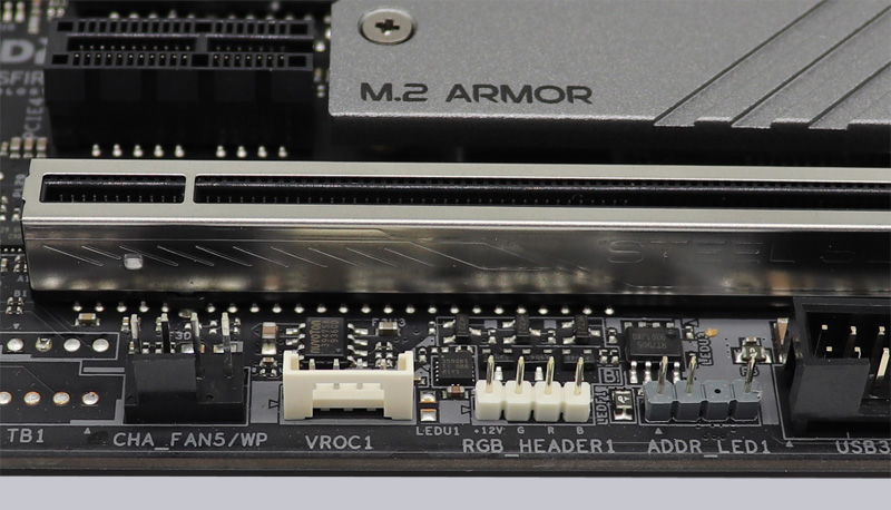
With the Creator series, however, ASRock has no RGB lighting integrated on the chipset cooler or I/O cover, so an external solution via the RGB/aRGB headers would be necessary if desired.
The RGB/aRGB headers are controlled by the included ASRock Polychrome RGB LED software. There you select for example the colors in a RGB color selector and can set whether the RGB headers should be controlled separately or together with the aRGB headers. Of course you can also disable the lighting completely or apply it to all connectors at the same time depending on the effect.
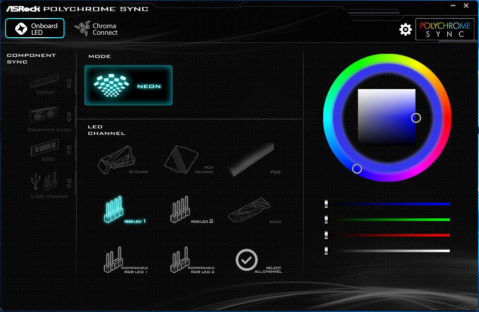
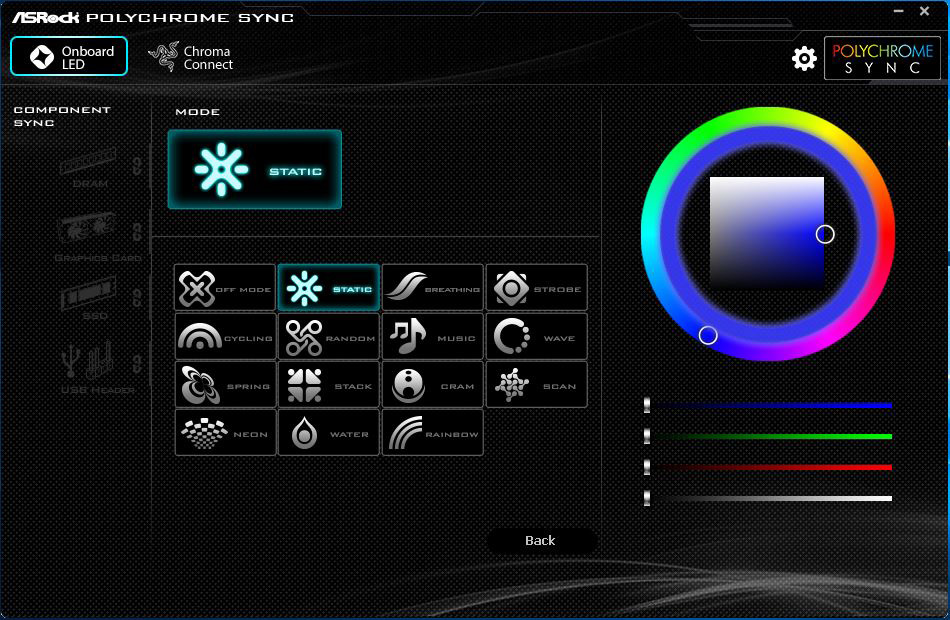
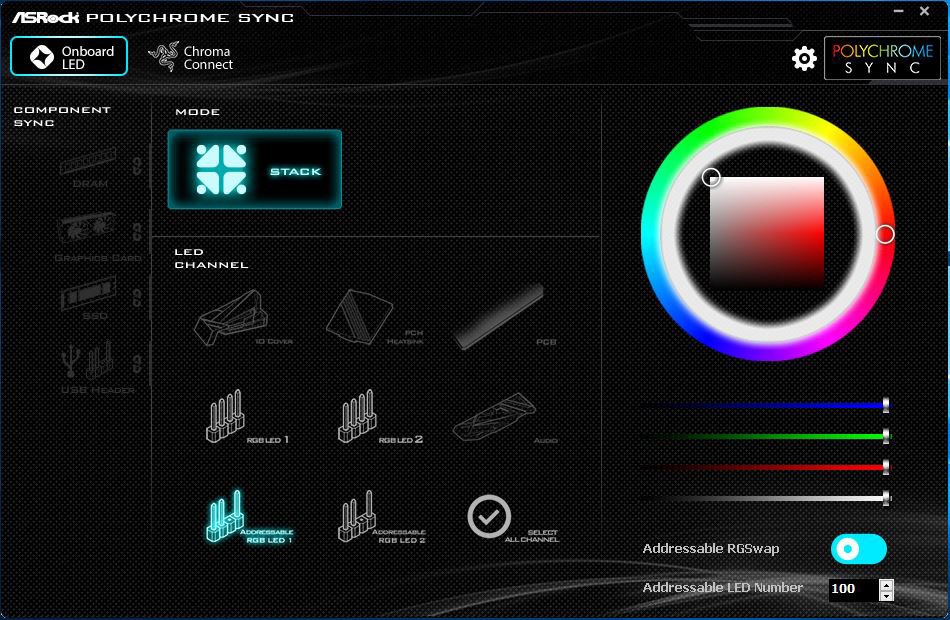
In the ASRock Polychrome RGB LED software, for example, you select the colors in an RGB color selector. The lighting can of course be deactivated completely. And with the addressable RGB LED connectors you even get completely new RGB features such as Spring, Meteor, Stack, Rainbow, etc.
So there are a lot of great RGB effects for externally connected LED Stripes, which we presented in the ASRock Polychrome RGB Software Video on our OCinside YouTube channel.
Note: Please allow our cookies first to see this external content!
By the way, you can address up to 100 LEDs individually.
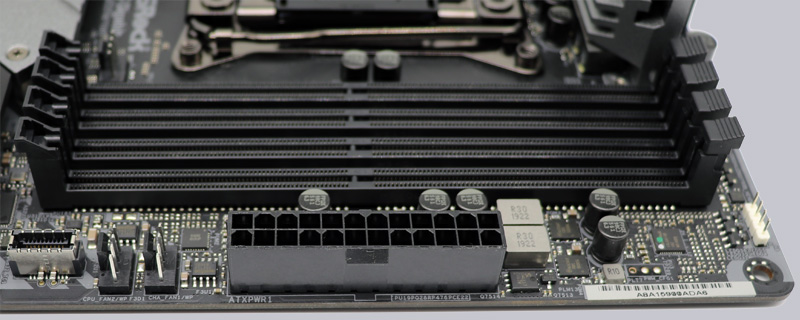
But let’s get back to the equipment. On the left, you can see the front USB 3.2 Gen2 type-C connector, two of the seven fan connectors, the 24-pin ATX power connector, some Nichicon capacitors and the second RGB connector.
Voltage Regulator and Heat Sink …
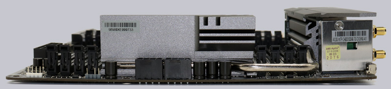
The picture shows the side view of the motherboard with the large heat sink on the MOSFETs. More exactly it is a heatsink, which rests on a row of MOSFETs and was connected to a second heatsink by means of a heatpipe.
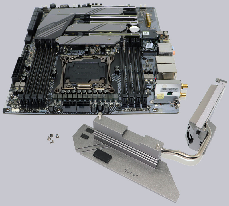
Since the heatsink also serves as I/O cover, the MOSFET heatsink can be screwed off directly. Here you can see the two unmounted aluminum heatsinks, one of which is pressed onto the voltage converters by means of a thermal pad.
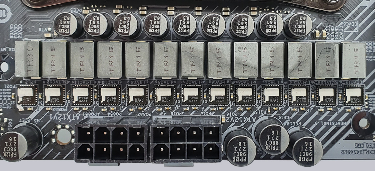
Under the heat sinks of the ASRock X299 Creator, the so-called Smart Power Stage area is cooled, which in the ASRock X299 Creator consists of a total of 13 Intersil ISL99227B 60A 5V PWM controllers with integrated UVLO fault, overtemperature and overcurrent protection.
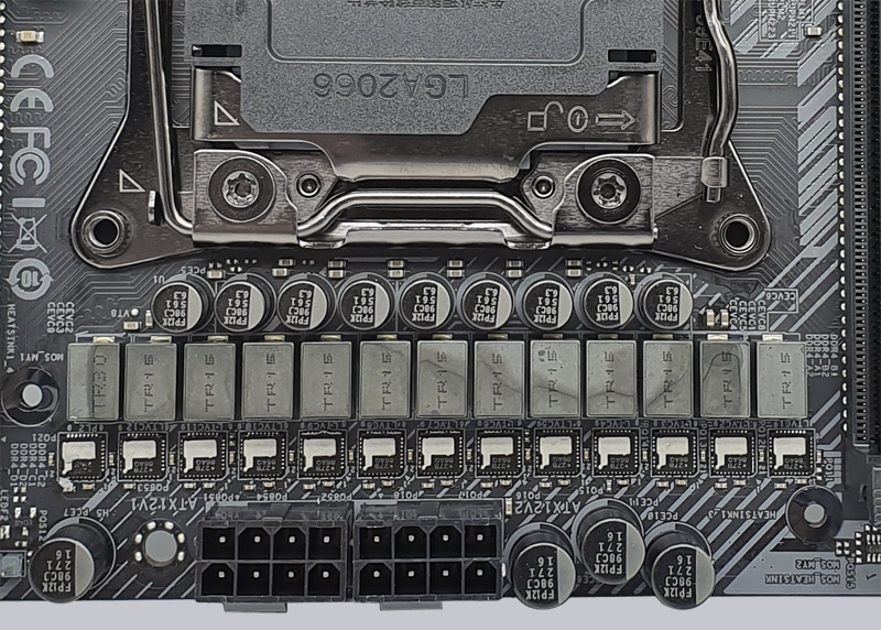
Here you see again the Intersil 27B MOSFETs at the 60A coils, which are responsible for the power supply of the Intel CPU. The power supply is realized via the Dual Power Connector, i.e. two 8-pin 12V power supply connectors.
Equipment …
The ASRock X299 Creator has many features such as ASRock Tuning Tool, ASRock Instant Flash, ASRock Internet Flash, ASRock Easy RAID Installer, 13 Power Phase Design, Digi Power, RGB, Polychrome RGB and ASRock FAN-Tastic Tuning.
Expansion cards …
The motherboard offers four PCI Express 3.0 x16 slots for AMD CrossFireX or nVidia SLI and one PCI Express 3.0 x1 slot.
Memory …
The ASRock X299 Creator Board can be equipped with up to eight DDR4 modules and can be upgraded up to 256 GB RAM depending on the operating system used (see list). Here you can see a picture of the eight DDR4 memory slots with Quad Channel support.
The Intel LGA 2066 motherboard supports DDR4 memory modules and can be optimized in the BIOS with an Intel Skylake-X processor for DDR4-2666 Quad Channel modules and with an Intel Cascade Lake-X for DDR4-2933 Quad Channel modules. The UEFI offers adaptations from DDR4-800 up to DDR4-4400.
Thanks to XMP support (Extreme Memory Profile), XMP memory modules can be set correctly with a mouse click in the UEFI, but more about this later. Which exact RAM modules are officially supported, one should read before the purchase at ASRock on the Memory Support page.
Hard disk drive connectors …
The ASRock X299 Creator offers a total of ten angled SATA3 ports, two of which are controlled via the ASMedia ASM1061 controller.
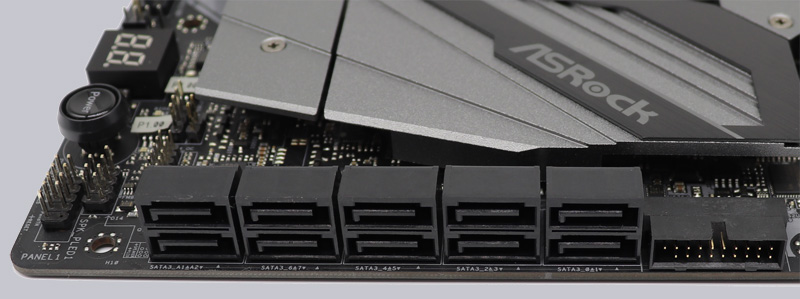
The SATA3 ports support RAID 0, RAID 1, RAID 5, RAID 10, NCQ, AHCI and the hot plug function in AHCI mode (AHCI stands for Advanced Host Controller Interface and should be selected for SSDs in UEFI). Thanks to UEFI BIOS, drives with more than 2TB can also be used for Windows 10 x64 installation. The installation of the drivers went without problems in Windows 10, so the 64 bit Windows 10 installation was done quickly.
The RAID drivers can be installed via the Easy RAID Installer point in UEFI. The drivers for Windows 10 are delivered on DVD and are also available for download on the ASRock support page.
USB and Firewire …
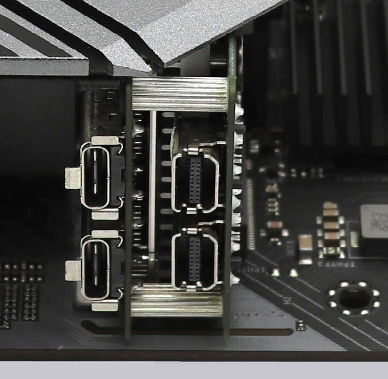
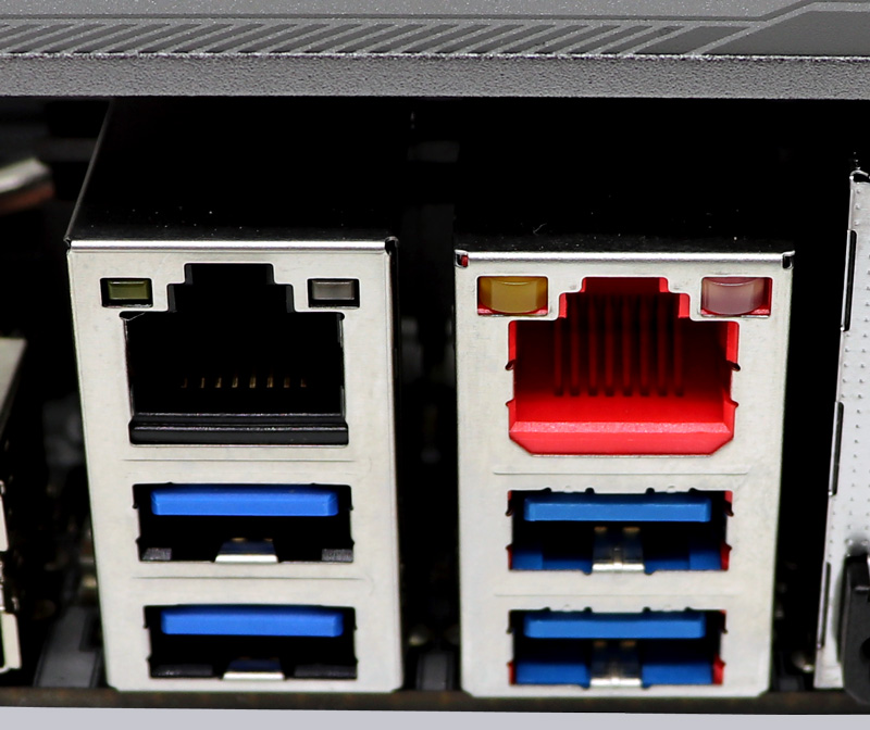
The ASRock X299 Creator has two USB 2.0 ports, four USB 3.2 Gen1 ports and two USB 3.2 Gen2 ports on the ATX panel. On the left half of the picture you can see the two USB 2.0 ports, in the middle the four USB 3.2 Gen1 ports and on the right half of the picture you can see the two USB 3.2 Gen2 type-C ports, which can be plugged in on both sides and are excellent for image output.
An important feature for USB-C monitor owners is the combination of the two USB 3.2 Gen2 Thunderbolt3 ports with the two Mini DisplayPort inputs, because via mini DisplayPort to DisplayPort cable the graphic card signal can be looped through to the Thunderbolt USB-C ports!
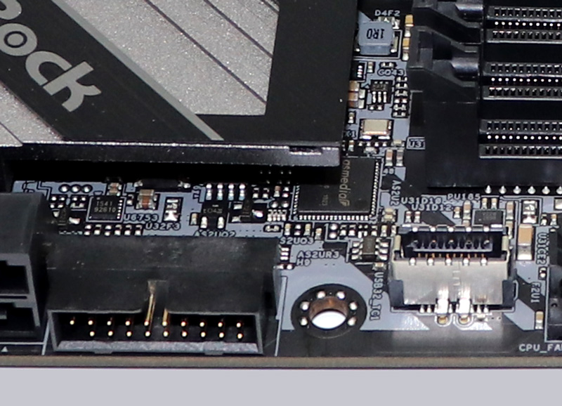
Two internal USB 2.0 ports for up to four optional USB 2.0 ports and a USB 3.2 Gen1 header for up to two optional USB 3.2 Gen1 ports are available. The 20-pin header can be connected either to an optionally available USB3.0 front panel or to an enclosure with USB3.0 support. Another new feature is the USB 3.2 Gen2 front panel type-C connector, which allows 10 Gbps on the front panel front panel housing.
Hint: If you are wondering about the different descriptions of the USB ports, we would like to explain the differences between USB 3.0, USB 3.1 Gen1, USB 3.1 Gen2, USB 3.2 Gen1 and USB 3.2 Gen2. Regarding the USB power for charging devices, USB 2.0 officially provides 5V with 0.5A, thus 2.5W, and USB 3.0/3.1/3.2 officially provides 5V with 0.9A, thus 4.5W, and USB 3.0/3.1/3.2 officially provides 5V with 0.9A, respectively ASRock with Type-A connector up to 1.5A, and USB Type-C connector 5V with 3A, thus 15W (1A in sleep state). Furthermore, the transfer rates of the USB ports are also different. USB 3.1 Gen1 was formerly called USB 3.0 and is therefore identically, they both deliver up to 5 GBit/s. USB 3.1 Gen2 delivers up to 10 Gbps. In addition, there is USB 3.2 Gen2x2, which allows doubling up to 20 GBit/s. A special feature is also available for the Intel JHL7540 Thunderbolt 3 protocol, which allows up to 40 GBit/s! Here you are again the possible transfer rates in a table.
| USB Interface Comparison | ||
| Transfer rate | ||
| Interface | theoretical | practical |
| USB 2.0 | 480 MBit/s | 30 MByte/s |
| USB 3.0 | 5 GBit/s | 450 MByte/s |
| USB 3.1 Gen1 | 5 GBit/s | 450 MByte/s |
| USB 3.1 Gen2 | 10 GBit/s | 800 MByte/s |
| USB 3.2 Gen1 | 5 GBit/s | 400 MByte/s |
| USB 3.2 Gen2 | 10 GBit/s | 800 MByte/s |
| USB 3.2 Gen2x2 | 2×10 GBit/s | 1600 MByte/s |
Network …
The ASRock X299 Creator has an Aquantia AQC107 chip for 10 Gigabit LAN and was also equipped with an Intel I219V, with which an additional 10/100/1000 network port is realized on the ATX panel. The Intel LAN port is WoL capable, offers LAN cable detection, supports energy efficient Ethernet according to the 802.3az standard, PXE and more.
In addition, the X299 Creator offers the new WLAN 2.4 GHz/5 GHz Dual Band Intel 802.11a/b/g/n/ax with up to 2400 Mbps transfer rate and Bluetooth 5.0.
Sound …
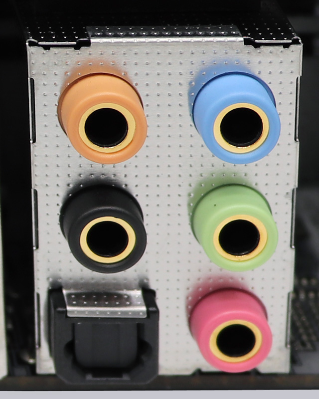
Also the ASRock X299 Creator motherboard has again the better Realtek ALC1220 Audio Codec with Content Protection, 120dB SNR DAC, TI NE5532 Premium Headset Amplifier and Purity Sound 4, which supports 7.1 surround sound and outputs it for example analog over 5x 3.5mm jacks on the ATX panel or over the internal front panel audio connector. There is also an optical SPDIF digital output and premium Blu-Ray support. So an additional soundcard with digital outputs is not necessary for most users.
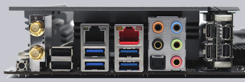
ATX Backpanel connections …
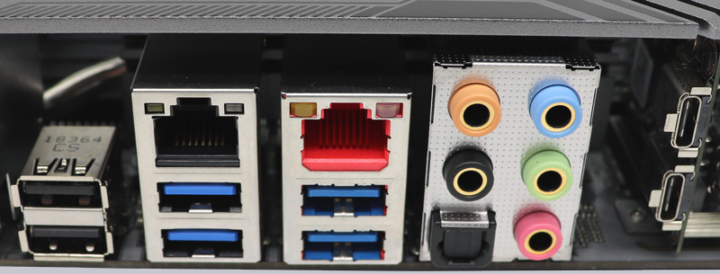
From left to right you see the Clear CMOS button, two WiFi antenna connectors, 2x USB 2.0, RJ45 Gigabit LAN and 2x USB 3.2 Gen1, RJ45 10 Gigabit LAN and 2x USB 3.2 Gen1, optical SPDIF output, 5x 3.5mm jacks for sound, 2x USB 3.2 Gen2 Type-C Thunderbolt 3 and 2x Mini DisplayPort inputs.
Test System …
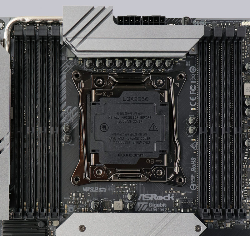
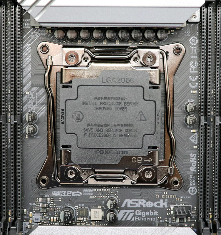
Now we come to the Intel LGA 2066 CPU socket. The socket was again equipped with two levers, which are operated one after the other to press the CPU evenly onto the pins in the socket. As always, you should never touch the contacts during installation or even bend the contacts in the socket. When storing or transporting the socket, it is essential that you fit the protective cap on the socket. If the pins are bent and the mainboard doesn’t work anymore, we are available for help and advice in Intel Forum.
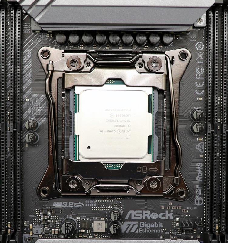
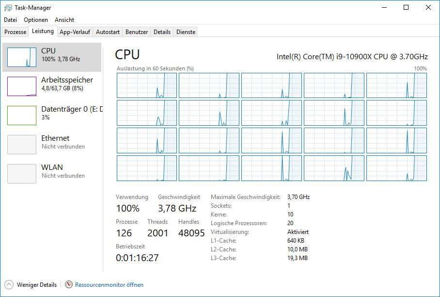
We first equipped the test system with the Intel Core i9-7900X Skylake-X CPU for comparison with previous results and then tested the system with a very recent Intel Core i9-10900X Cascade Lake-X CPU!
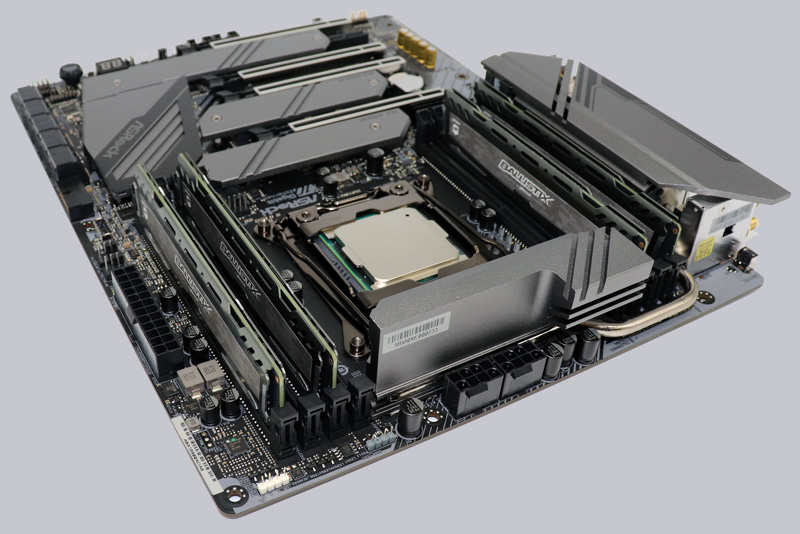
Here you can see the four DDR4 modules from Crucial in the ASRock X299 Creator motherboard. To give the Intel LGA 2066 CPU a high memory throughput, we used four Ballistix Sport DDR4 2666 16 GB BLS16G4D26BFSB modules. Intel Cascade Lake-X and Intel Skylake-X with 28 or 55 PCIe lanes processors support Quad Channel Mode, Intel processors with 16 PCIe lanes however only support Dual Channel Mode. So four of the eight possible memory modules are used on the Intel X299 Creators motherboard to get Quad Channel support with the Intel Core i9-7900X or with the Intel Core i9-10900X CPU. The Intel Cascade Lake-X processors even support DDR4-2933.
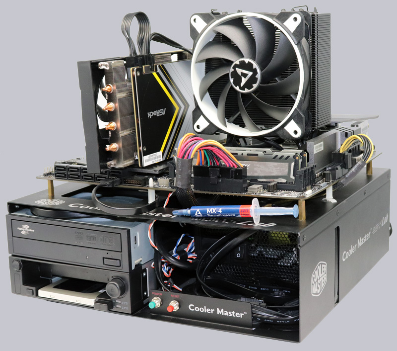
Here you can see the Intel LGA 2066 test system with Arctic Freezer 33 TR cooler and the fresh ARCTIC MX4 thermal compound, the new ASRock Radeon RX 5700 Challenger D 8G OC graphics card and Icy Dock MB171SP-B Turbo Swap removable frame for quick exchange of the HDD or SSD.
This is how the 10 cores (20 threads) of the Intel Core i9-10900X CPU look in the Windows 10 task manager at Prime95 Full Load.
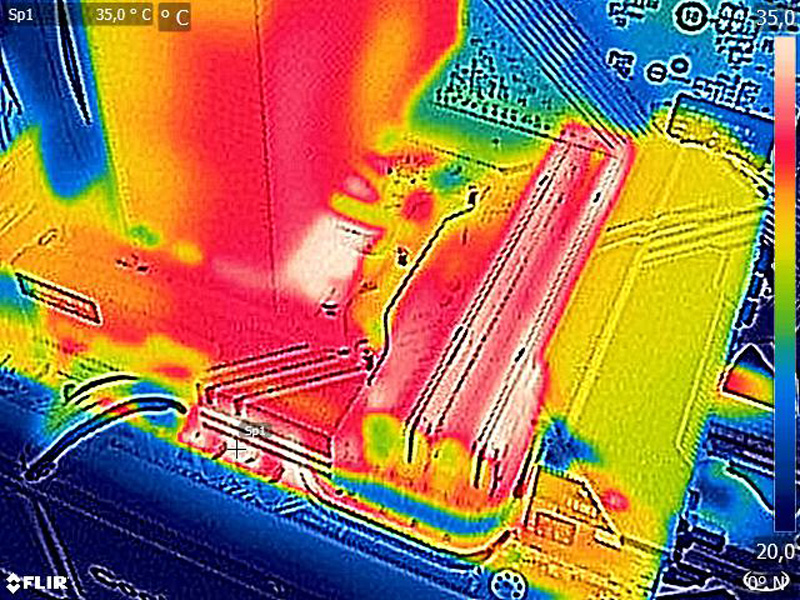
As you can see on the thermal image of the ASRock X299 Creator PC, the waste heat of the voltage regulators and coils is conducted to the second MOSFET heatsink via the I/O panel by means of a heatpipe, thus ensuring better heat dissipation.
ASRock X299 Creator BIOS and Overclocking …